| View previous topic :: View next topic |
| Author |
Message |
Jesito


Joined: 24 Aug 2007
Posts: 5745
Location: Olivella, Catalonia, (Spain)
Expire: 2015-01-07
|
 Posted: Thu Oct 09, 2008 4:50 am Post subject: The shutter speed meter project Posted: Thu Oct 09, 2008 4:50 am Post subject: The shutter speed meter project |
 |
|
Jesito wrote:
Hi colleagues,
As you know, I'm behind such a project since quite long ago.
I've been taking some notes and putting them into my server whilst it's under development (it's easier to me for changes), but will be a forum article when finished.
If you want to take a glimpse to the work in progress, please go to
http://watersmurf.homelinux.com/photo/diy/shutterspeed.html
Open to hear your ideas, suggestions, etc.
Jes.
_________________
Jesito, Moderator 
Jesito's backsack:
Zooms Sigma 70-300, Tamron 35-135 and 70-210 short, 70-210 long, 28-70 CF Macro, 35-70, 35-80, Vivitar 70-210 KA, Tamron 70-250.
Fixed Industar-50, , Tamron 24mm, Tamron 135mm, Sands Hunter 135mm, Pancolar 50mm, Volna-3, many Exakta lenses
DSLR SIGMA SD9 & SD14, EOS 5D, Sony A700 and NEXF3, Oly E-330, E-400, E-450, E-1
TLR/6x6/645 YashicaMat, Petri 6x45, Nettar, Franka Solida, Brilliant
SLR Minolta X300, Fuji STX II, Praktica VLC3, Pentax P30t, EXA500, EXA 1A, Spotmatic(2), Chinon CM-4S, Ricoh, Contax, Konica TC-X , Minolta 5000, 7000i, 3Sxi, EOS 500 and CX
Rangefinders Chinon 35EE, Konica C35 auto, Canonet 28, Yashica Lynx, FED-2, Yashica electro 35, Argus C3 & C4, Regula Cita III, Voigtlander Vitoret (many), Welta Welti-I, Kodak Signette 35, Zorki-4, Bessa-R & L, Minolta Weathermatic, olympus XA2
Compact Film Konica C35V, Voigtlander Vitorets, Canon Prima Super 105, Olympus XA2 and XA3
Compact Digital Olympus C-5050, Aiptek Slim 3000, Canon Powershot A540, Nikon 5200, SIGMA DP1s, Polaroid X530, IXUS55, Kodak 6490, Powershot G9 and G10
CSCCanon EOS-M, Samsung NX100 and NX210, Lumix G5, NEX-F3 |
|
| Back to top |
|
 |
Xpres


Joined: 11 Dec 2007
Posts: 964
Location: UK
Expire: 2014-10-28
|
| Posted: Thu Oct 09, 2008 9:04 am Post subject: |
|
|
Xpres wrote:
Jes - What a great article, thanks for posting. 
I'll have to stick to the audio method as an oscilloscope and and the accompanying leap in technical know how is beyond me. But I do like the idea of a laser pointer as a light source - I was using a desk lamp...
For testing rather old shutters, often with only three or four speeds, I wonder if one might not just take readings relative to each other so the absolute result is not important - perhaps using one second as a base?
_________________
Film... and sometimes SD14, 5D2 and some other suff! |
|
| Back to top |
|
|
LucisPictor

Joined: 26 Feb 2007
Posts: 17633
Location: Oberhessen, Germany / Maidstone ('95-'96)
Expire: 2013-12-03
|
| Posted: Thu Oct 09, 2008 11:05 am Post subject: |
|
|
LucisPictor wrote:
That's professional, Jes!
_________________
Personal forum activity on pause every now and again (due to job obligations)!
Carsten, former Moderator 
Things ON SALE
Carsten = "KAPCTEH" = "Karusutenu" | T-shirt?.........................My photos from Emilia: http://www.schouler.net/emilia/emilia2011.html
My gear: http://retrocameracs.wordpress.com/ausrustung/
Old list: http://forum.mflenses.com/viewtopic.php?t=65 (Not up-to-date, sorry!) | http://www.lucispictor.de | http://www.alensaweek.wordpress.com |
http://www.retrocamera.de |
|
| Back to top |
|
|
Orio

Joined: 24 Feb 2007
Posts: 29545
Location: West Emilia
Expire: 2012-12-04
|
| Posted: Thu Oct 09, 2008 11:45 am Post subject: |
|
|
Orio wrote:
Hat off, Jes. I would never be able to imagine such a thing, let alone build it.
_________________
Orio, Administrator
T*
NE CEDE MALIS AUDENTIOR ITO
Ferrania film is reborn! http://www.filmferrania.it/
Support the Ornano film chemicals company and help them survive!
http://forum.mflenses.com/ornano-chemical-products-t55525.html |
|
| Back to top |
|
|
Jesito
Joined: 24 Aug 2007
Posts: 5745
Location: Olivella, Catalonia, (Spain)
Expire: 2015-01-07
|
| Posted: Thu Oct 09, 2008 1:22 pm Post subject: |
|
|
Jesito wrote:
Thanks, colleagues, but this is just "work in progress", maybe it ends in nothing...
But I try to compile all the information I've been able to get, plus my own ideas.
Tonight I expect to try the "oscilloscope/laser" combo, I'll take some pictures.
Jes.
_________________
Jesito, Moderator
Jesito's backsack:
Zooms Sigma 70-300, Tamron 35-135 and 70-210 short, 70-210 long, 28-70 CF Macro, 35-70, 35-80, Vivitar 70-210 KA, Tamron 70-250.
Fixed Industar-50, , Tamron 24mm, Tamron 135mm, Sands Hunter 135mm, Pancolar 50mm, Volna-3, many Exakta lenses
DSLR SIGMA SD9 & SD14, EOS 5D, Sony A700 and NEXF3, Oly E-330, E-400, E-450, E-1
TLR/6x6/645 YashicaMat, Petri 6x45, Nettar, Franka Solida, Brilliant
SLR Minolta X300, Fuji STX II, Praktica VLC3, Pentax P30t, EXA500, EXA 1A, Spotmatic(2), Chinon CM-4S, Ricoh, Contax, Konica TC-X , Minolta 5000, 7000i, 3Sxi, EOS 500 and CX
Rangefinders Chinon 35EE, Konica C35 auto, Canonet 28, Yashica Lynx, FED-2, Yashica electro 35, Argus C3 & C4, Regula Cita III, Voigtlander Vitoret (many), Welta Welti-I, Kodak Signette 35, Zorki-4, Bessa-R & L, Minolta Weathermatic, olympus XA2
Compact Film Konica C35V, Voigtlander Vitorets, Canon Prima Super 105, Olympus XA2 and XA3
Compact Digital Olympus C-5050, Aiptek Slim 3000, Canon Powershot A540, Nikon 5200, SIGMA DP1s, Polaroid X530, IXUS55, Kodak 6490, Powershot G9 and G10
CSCCanon EOS-M, Samsung NX100 and NX210, Lumix G5, NEX-F3 |
|
| Back to top |
|
|
Jesito
Joined: 24 Aug 2007
Posts: 5745
Location: Olivella, Catalonia, (Spain)
Expire: 2015-01-07
|
| Posted: Wed Oct 22, 2008 4:21 pm Post subject: |
|
|
Jesito wrote:
Well, well, well...
In the first place, and taking into account that no everybody has an oscilloscope at hand, I've tested the soundcard version. Peter was waiting for this to start building his own one... And this seems to work!.
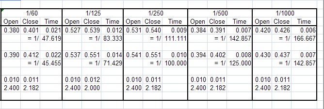
This is the schematic:
(I used a 4k7 resistor instead the 3k9 one, no problem... Resistors are like film latitude...  ). ).
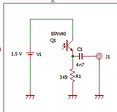
I built it on a perf board, and since it's a prototype, it has been built the dirty way: Batteries soldered, etc, just to see if it works.
Also not using the intended laser as a light source. I've used a hi-bright LED diode instead.


The layout is critical. Some physical stability is needed to be useable... But for a prototype everything is valid. I used a "third hand" device to hold the board with the phototransistor:

The ligth source comes from a tiltable lamp, cannibalized for this purpose:
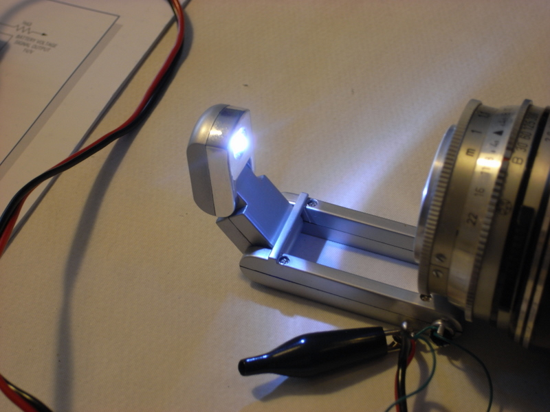
The board in place:

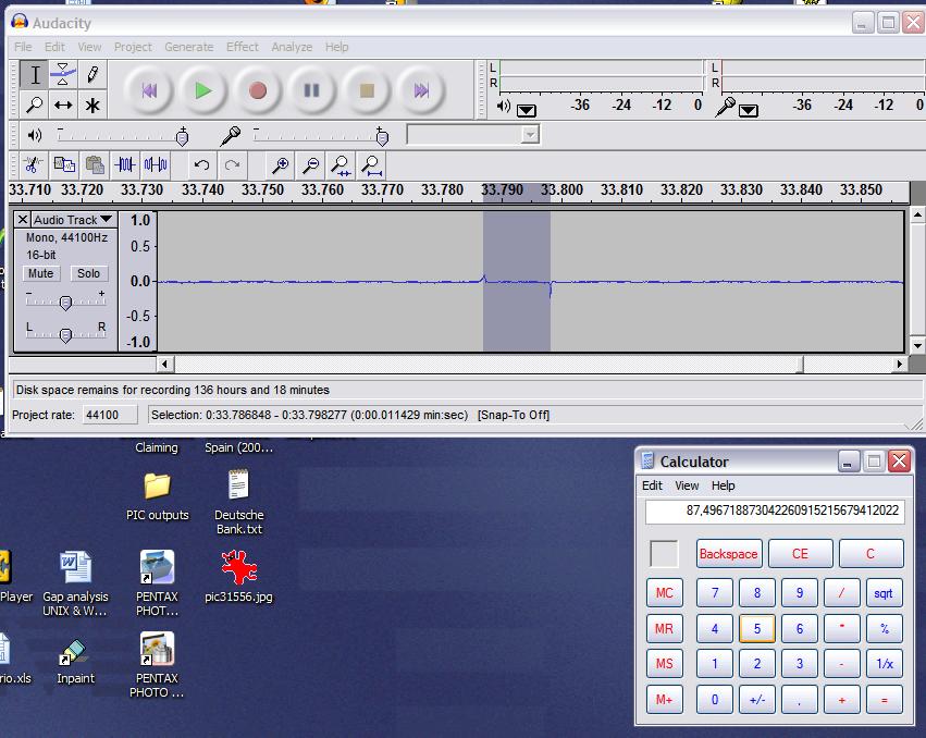
Finally, measuring is quite easy: I used Audacity, started recording a track, fired the shutter at 1/300 speed. As soon as I fired the shutter, I stopped recording the audio track. There was a tiny mark that had to be widened a lot to be able to measure the width. By selecting the space in between the two marks, you get the time at the bottom of the screen. It has to be inverted (1/x) to get the speed, that in this case is 1/87,49 far slower than it should be... Not strange, the shutter gets blocked at lower speeds, so it need a deep cleaning and review.
And that's all, folks!
Jes.
_________________
Jesito, Moderator
Jesito's backsack:
Zooms Sigma 70-300, Tamron 35-135 and 70-210 short, 70-210 long, 28-70 CF Macro, 35-70, 35-80, Vivitar 70-210 KA, Tamron 70-250.
Fixed Industar-50, , Tamron 24mm, Tamron 135mm, Sands Hunter 135mm, Pancolar 50mm, Volna-3, many Exakta lenses
DSLR SIGMA SD9 & SD14, EOS 5D, Sony A700 and NEXF3, Oly E-330, E-400, E-450, E-1
TLR/6x6/645 YashicaMat, Petri 6x45, Nettar, Franka Solida, Brilliant
SLR Minolta X300, Fuji STX II, Praktica VLC3, Pentax P30t, EXA500, EXA 1A, Spotmatic(2), Chinon CM-4S, Ricoh, Contax, Konica TC-X , Minolta 5000, 7000i, 3Sxi, EOS 500 and CX
Rangefinders Chinon 35EE, Konica C35 auto, Canonet 28, Yashica Lynx, FED-2, Yashica electro 35, Argus C3 & C4, Regula Cita III, Voigtlander Vitoret (many), Welta Welti-I, Kodak Signette 35, Zorki-4, Bessa-R & L, Minolta Weathermatic, olympus XA2
Compact Film Konica C35V, Voigtlander Vitorets, Canon Prima Super 105, Olympus XA2 and XA3
Compact Digital Olympus C-5050, Aiptek Slim 3000, Canon Powershot A540, Nikon 5200, SIGMA DP1s, Polaroid X530, IXUS55, Kodak 6490, Powershot G9 and G10
CSCCanon EOS-M, Samsung NX100 and NX210, Lumix G5, NEX-F3 |
|
| Back to top |
|
|
Throndor


Joined: 15 Sep 2008
Posts: 157
Location: Ankara / TURKEY
|
| Posted: Thu Oct 23, 2008 10:58 am Post subject: |
|
|
Throndor wrote:
Nice one Jes,
Isn't it simpler to measure the shutter speed with a disc on a motor and a digital camera..
_________________
Omer
Pentax K100D super
Pentax DA 18-55 AL
Pentax SMC-FA 50 f/1.4
Aus Jena Pancolar 50/1.8 (Zebra)
Carl Zeiss Jena Sonnar 135/3.5
Varexon 35/2.8
Helios 44-2 58/2
|
|
| Back to top |
|
|
Xpres
Joined: 11 Dec 2007
Posts: 964
Location: UK
Expire: 2014-10-28
|
| Posted: Thu Oct 23, 2008 12:13 pm Post subject: |
|
|
Xpres wrote:
| Throndor wrote: |
Nice one Jes,
Isn't it simpler to measure the shutter speed with a disc on a motor and a digital camera.. |
I'm intrigued - could you expand on that...?
_________________
Film... and sometimes SD14, 5D2 and some other suff! |
|
| Back to top |
|
|
Throndor
Joined: 15 Sep 2008
Posts: 157
Location: Ankara / TURKEY
|
| Posted: Thu Oct 23, 2008 6:02 pm Post subject: |
|
|
Throndor wrote:
| Xpres wrote: |
| Throndor wrote: |
Nice one Jes,
Isn't it simpler to measure the shutter speed with a disc on a motor and a digital camera.. |
I'm intrigued - could you expand on that...? |
get a harddisk motor.. thats very cheap and one of the most common things to find in a junkyard...
You attach a cardboard disc on the motor.. and place a dot on the disc..
What you do is take a film camera..place the disc in front of its lens..open the film door..place your digital cam behind the shutter..
You probably have guessed it by now..
Set your digicam to a speed like 1-2 sec.. press shutter release then quickly press the shutter on the film cam in that 1-2 sec interval..
So you took a photo of the turning disc through the film cameras shutter.. that dot you placed on the disc will have a radial blur as the disc was turning..
If your know the RPM of your motor..then you can measure the angle of the radial blur in photoshop and calculate the shutter speed..
Lets say you got a motor from a 7200 rpm harddisk.. 7200 rotations per minute = 120 rot.s per second.. so practicaly the slowest you can measure is shutter speed of 1/120..but you can measure any speed faster than that.. get a slower motor and you can measure slower speeds.. Get a faster one and you can measure shutter speeds like 1/60.000 sec...
This is actually my variation on a method thats already being used by extreme shutter speed digital photography.. when you take a pic at 1/20.000-60.000 virtual shutter speed all you can do to measure your speed is shoot this kind of rotating disc and measure it..
If you never heard this kind of shutter speeds and are curious about them, here is some extra info on it..I haven't tried so this is what i think i know correctly..
When you want a dimmer light from a Xenon flash, what it does is not decrease the intensity of its output but decrease its light emitting time.. Some of them can get to speeds of 1/60.000 or so.. You take a scene with narrow aperture and say like 1/8000 speed..what happens..not enough light and underexporuse.. But within that 1/8000 sec, if you set off a xenon flash with a speed of 1/60.000 (they use laser flash triggers) than all of the exposure you get is from that 1/60.000 flash lit moment..So you get really fast photography..
Get a cat.. make a soap bubble.. cat jumps at it to pop it up.. you take a photo..so fast.. that the bubble has a hole where the cats claw touched, the bubble has lost its uniform shape but you can clearly see it as a deflating baloon..
_________________
Omer
Pentax K100D super
Pentax DA 18-55 AL
Pentax SMC-FA 50 f/1.4
Aus Jena Pancolar 50/1.8 (Zebra)
Carl Zeiss Jena Sonnar 135/3.5
Varexon 35/2.8
Helios 44-2 58/2
|
|
| Back to top |
|
|
peterqd

Joined: 28 Feb 2007
Posts: 7448
Location: near High Wycombe, UK
Expire: 2014-01-04
|
| Posted: Thu Oct 23, 2008 10:36 pm Post subject: |
|
|
peterqd wrote:
Very interesting Omer, thankyou. I believe a rotating disk idea was used when the speed of light was first measured. In the old days of photography, when using a flash meant setting fire to some Magnesium powder, the technique was to open the shutter with the bulb, fire the flash by hand with a spark igniter and then close the shutter. The speed of the ignition of the powder was so slow that the shutter might be open for many seconds. Modern cameras do exactly the same but much faster, the flash sync speed is the fastest speed where the first shutter curtain is fully open before the second curtain starts to close.
_________________
Peter - Moderator |
|
| Back to top |
|
|
Jesito
Joined: 24 Aug 2007
Posts: 5745
Location: Olivella, Catalonia, (Spain)
Expire: 2015-01-07
|
| Posted: Mon Nov 03, 2008 4:44 am Post subject: |
|
|
Jesito wrote:
| Throndor wrote: |
get a harddisk motor.. thats very cheap and one of the most common things to find in a junkyard...
You attach a cardboard disc on the motor.. and place a dot on the disc..
What you do is take a film camera..place the disc in front of its lens..open the film door..place your digital cam behind the shutter..
You probably have guessed it by now..
Set your digicam to a speed like 1-2 sec.. press shutter release then quickly press the shutter on the film cam in that 1-2 sec interval..
So you took a photo of the turning disc through the film cameras shutter.. that dot you placed on the disc will have a radial blur as the disc was turning..
If your know the RPM of your motor..then you can measure the angle of the radial blur in photoshop and calculate the shutter speed..
Lets say you got a motor from a 7200 rpm harddisk.. 7200 rotations per minute = 120 rot.s per second.. so practicaly the slowest you can measure is shutter speed of 1/120..but you can measure any speed faster than that.. get a slower motor and you can measure slower speeds.. Get a faster one and you can measure shutter speeds like 1/60.000 sec...
This is actually my variation on a method thats already being used by extreme shutter speed digital photography.. when you take a pic at 1/20.000-60.000 virtual shutter speed all you can do to measure your speed is shoot this kind of rotating disc and measure it..
If you never heard this kind of shutter speeds and are curious about them, here is some extra info on it..I haven't tried so this is what i think i know correctly..
When you want a dimmer light from a Xenon flash, what it does is not decrease the intensity of its output but decrease its light emitting time.. Some of them can get to speeds of 1/60.000 or so.. You take a scene with narrow aperture and say like 1/8000 speed..what happens..not enough light and underexporuse.. But within that 1/8000 sec, if you set off a xenon flash with a speed of 1/60.000 (they use laser flash triggers) than all of the exposure you get is from that 1/60.000 flash lit moment..So you get really fast photography..
Get a cat.. make a soap bubble.. cat jumps at it to pop it up.. you take a photo..so fast.. that the bubble has a hole where the cats claw touched, the bubble has lost its uniform shape but you can clearly see it as a deflating baloon.. |
Seems interesting, Throndor, but IMHO the photodevice setup is much simpler, precise and cheaper.
In the first place, only very old harddisks have such a motor. Since several years, hard disk motors are "brushless" and they do not turn if you don't apply a digital signal in sequence.
Besides having a digital sequencer you also need a power supply (you might get one from an old PC). But the ensemble would be much cumbersome than the three cheap components you need to setup the photodevice one.
With the photodevice system you can measure the shutter speed without having a lens in the camera. Measures are immediate and precise, you need only to invert the figure that the audio program gives you.
And the circuit is so simple than even an unexperienced person could iron it in a few minutes.
Anyway I appreciate very much your suggestion, It's interesting to see how the human mind is able to devise such clever solutions. I admire those old scientists that with really basic tools were able of doing complex measures. Nowadays everything is under control of a microprocessor of some kind and we use to kill flies with cannon shots.
Thanks for sharing!
Jes.
_________________
Jesito, Moderator
Jesito's backsack:
Zooms Sigma 70-300, Tamron 35-135 and 70-210 short, 70-210 long, 28-70 CF Macro, 35-70, 35-80, Vivitar 70-210 KA, Tamron 70-250.
Fixed Industar-50, , Tamron 24mm, Tamron 135mm, Sands Hunter 135mm, Pancolar 50mm, Volna-3, many Exakta lenses
DSLR SIGMA SD9 & SD14, EOS 5D, Sony A700 and NEXF3, Oly E-330, E-400, E-450, E-1
TLR/6x6/645 YashicaMat, Petri 6x45, Nettar, Franka Solida, Brilliant
SLR Minolta X300, Fuji STX II, Praktica VLC3, Pentax P30t, EXA500, EXA 1A, Spotmatic(2), Chinon CM-4S, Ricoh, Contax, Konica TC-X , Minolta 5000, 7000i, 3Sxi, EOS 500 and CX
Rangefinders Chinon 35EE, Konica C35 auto, Canonet 28, Yashica Lynx, FED-2, Yashica electro 35, Argus C3 & C4, Regula Cita III, Voigtlander Vitoret (many), Welta Welti-I, Kodak Signette 35, Zorki-4, Bessa-R & L, Minolta Weathermatic, olympus XA2
Compact Film Konica C35V, Voigtlander Vitorets, Canon Prima Super 105, Olympus XA2 and XA3
Compact Digital Olympus C-5050, Aiptek Slim 3000, Canon Powershot A540, Nikon 5200, SIGMA DP1s, Polaroid X530, IXUS55, Kodak 6490, Powershot G9 and G10
CSCCanon EOS-M, Samsung NX100 and NX210, Lumix G5, NEX-F3 |
|
| Back to top |
|
|
peterqd
Joined: 28 Feb 2007
Posts: 7448
Location: near High Wycombe, UK
Expire: 2014-01-04
|
| Posted: Wed Feb 03, 2010 4:32 pm Post subject: |
|
|
peterqd wrote:
Hi, time for an update on the MFL International Shutterspeed Meter Project (MFLISMP - not quite as complicated as the CERN Project but a much nicer acronym!). At least this is my half of it, I'm hoping Jes will arrive soon.
Following on from the Spotmatic battery problem, Jes and I got talking about the shutter speed meter which he'd been working on. I needed to check the shutter speeds on a few cameras, so Jes's work interested me. There are several sites on the net with circuit diagrams of simple shutter testers using the PC soundcard and audio software. It seemed worth trying.
We started by thinking about a light source. Jes's cheap LED light wasn't giving good results, we needed something more directional and more intense, and Jes hit on the brilliant idea of using a laser pointer! We tried the very cheap Chinese ones on Ebay at first, but they turned out to be poor quality with a very short lifespan, so Jes visited his electronics store in Barcelona and bought some high quality laser elements and very kindly sent three of them to me, along with a few other components and even a bundle of different coloured wires! The beauty of these laser elements is that they require a 3v supply which can be taken from a USB port on the PC. I had an old USB cable handy so I was ready to start the Mark I prototype!
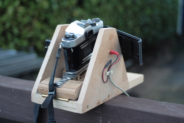
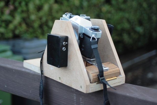
In the meantime, I'd been giving some thought to how to mount the laser and the camera and hold it steady while releasing the shutter. I had an old flat flash bracket with a long slot for adjustment and I worked out a way of mounting this on an MDF base, and by fixing it with a hinge I was able to adjust the camera vertically too, to centre the laser beam in the camera picture frame. Here's the finished test-bed. (This pic is actually Mark II - see lower down)

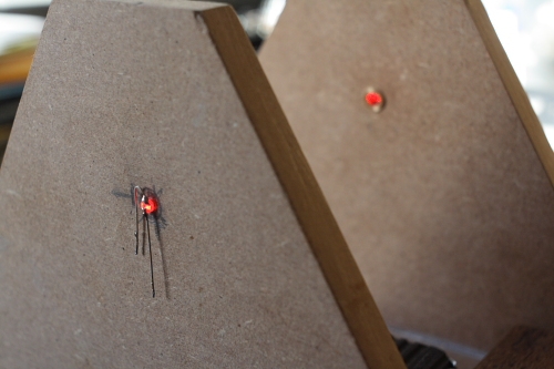
The laser and the receiving photodiode are mounted in holes drilled in the vertical sides of the contraption, and obviously the holes need to be lined up. This wasn't easy to do, having already fixed and glued the sides. Mark IV is going to have all the holes predilled together through both sides before fixing them. This pic shows the laser beam and the photodiode waiting to be connected to the PCB.

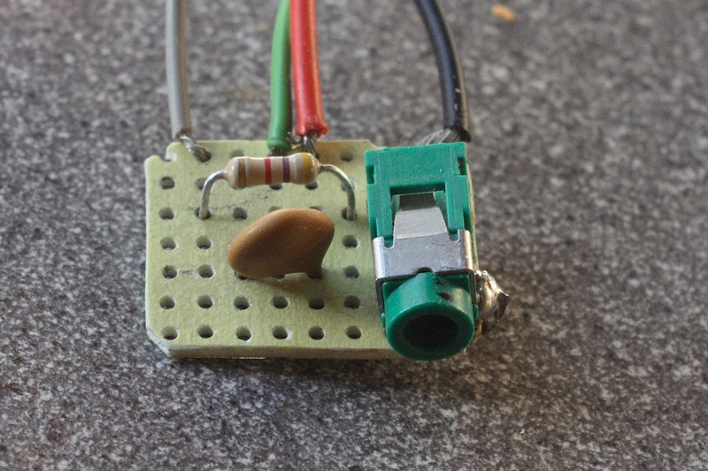
The photodiode acts like a simple switch, allowing current to pass when it is activated by light, so just a couple of wires are needed to run to the PCB. The PCB is just a small piece of perfboard with the components soldered on it, including a 3mm jack socket. There is also a 1.5v AAA battery wired in, not shown in the pic.

The setup was now ready for the first trial. I mounted a camera, plugged in the USB power cable and plugged the signal cable into the PCB socket and the Mic socket of my soundcard, and started recording the audio signal with Adobe Audition. The Audition screen can be set to show the time in seconds to three decimal places, ideal for measuring 1/1000 second exposures. At the same time I ran an Excel spreadsheet so I could enter the two time values taken from the screen and convert these into exposure times.
There was a definite blip for each shutter curtain on the signal trace and the time interval could be measured, but not very accurately. The diode has a slight delay which causes a curve on the signal trace, not a nice vertical line, so it was difficult to pinpoint the passing of each curtain. Another problem was keeping everything steady. Even with the test bed clamped down, holding the camera steady while winding and releasing the shutter is hard enough, but with a loose PCB, a battery and lots of loose wires hanging off it, it was very fiddly. The components needed to be mounted properly. We thought about the wavy signal trace and Jes had another great idea to add a variable resistor into the circuit in order to fine tune the signal. So I went to my local Maplins (like Radio Shack) and bought a box and battery holder, plus a few other components, including a 10k v. resistor, a panel-mounted jack socket and a power switch. All the components could now be mounted inside the box and screwed to the side of the test bed. The piece of perfboard wasn't needed any longer, so soldering everything together was very simple. This is Mark II:
I tested virtually all my cameras using this model, and it gave very interesting results. The additional resistor made a big difference. I could now see why one of the Spotmatics was overexposing, the 1/1000 speed was over 2 stops too slow! However, with just the one signal, I couldn't tell whether one curtain or both were running slow, and whether the exposure was consistent across the frame. I figured with two diodes and two lasers at a measured distance apart, and using the stereo Line-In input into the soundcard I could find out this information, and yesterday I finished Mark III. Besides the extra laser and diode, I raised the camera higher with a deeper section of wood so that it was level and the plane of the two beams was parallel with the shutter movement.
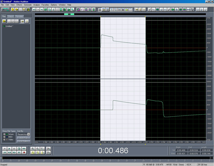
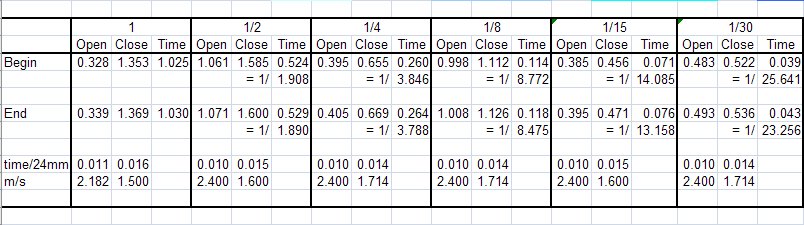
Here is a screenshot of the audio recording I made for the errant Spottie at 1/30 sec: As the first shutter curtain passes each beam it exposes the diode to the laser, the current is connected in the circuit and an audio signal is recorded on the PC. When the second curtain passes it turns off the current and the signal is stopped. This causes a blip on each of the stereo channels for each curtain, so four times can be recorded. The exposure time at each diode is the distance bewteen the two blips on each channel. The travel speed of each curtain can be calculated by measuring the time difference between the two channels.

On this picture, the section highlighted represents the exposure time at the first diode. You can see the start and finish times and the length of the selection in the panel at bottom right. In this case the length is .038 seconds, or about 1/26 sec. so the exposure is slightly too long. The exposure time at the second diode measures 1/23 seconds. This inaccuracy increases as the speeds get faster. At 1/1000 I recorded 1/166 and 1/142 secs - still over 2 stops too slow.
The design curtain travel speed for the Spottie is 14ms across the complete frame +/- 0.3 ms. This equates to a speed of just over 2.5 meters per second. The times I recorded gave speeds of 2.4 m/s for the first curtain and 2.14 m/s for the second. It is now clear how much each curtain tension needs to be adjusted.
The trace has another interesting feature. The light hitting one of the diodes makes a blip on the signal from the other diode. I think this might be due to light entering the black box though each diode, so I am going to try sticking some chewing gum over them! 
_________________
Peter - Moderator |
|
| Back to top |
|
|
ludoo

Joined: 18 Sep 2009
Posts: 1397
Location: Milan, Italy
Expire: 2011-12-05
|
| Posted: Wed Feb 03, 2010 4:57 pm Post subject: |
|
|
ludoo wrote:
Very interesting. Could you post a list of parts and a schematic for the updated version, with the stereo jack and vr? |
|
| Back to top |
|
|
Attila

Joined: 24 Feb 2007
Posts: 57865
Location: Hungary
Expire: 2025-11-18
|
| Posted: Wed Feb 03, 2010 5:04 pm Post subject: |
|
|
Attila wrote:
http://www.open.hr/~dpleic/photo/shutter_v2/shutter2.html
I am also thinking on it I found this.
_________________
-------------------------------
Items on sale on Ebay
Sony NEX-7 Carl Zeiss Planar 85mm f1.4, Minolta MD 35mm f1.8, Konica 135mm f2.5, Minolta MD 50mm f1.2, Minolta MD 250mm f5.6, Carl Zeiss Sonnar 180mm f2.8
|
|
| Back to top |
|
|
peterqd
Joined: 28 Feb 2007
Posts: 7448
Location: near High Wycombe, UK
Expire: 2014-01-04
|
| Posted: Wed Feb 03, 2010 6:16 pm Post subject: |
|
|
peterqd wrote:
The circuit I built is a lot simpler, but it has two diodes and two lasers. I didn't use the small capacitor shown in the PCB picture. The basic diagram is here: my diodes are 24mm apart, not 18.
http://www.kyphoto.com/classics/combinationtester.html
I used a 10k vr similar to this:
http://www.maplin.co.uk/Module.aspx?ModuleNo=6499
and the diodes are like this: (the clear one, not the black IR one)
http://www.maplin.co.uk/Module.aspx?ModuleNo=2242
Jes sent me the lasers, I'm not sure what values they are. They look like this:
http://www.maplin.co.uk/Module.aspx?ModuleNo=11712
You can find the box, sockets, power switch and the battery holder etc on the Maplins site too.
This is the spreadsheet showing the full results (split into 2 for readability.) The bottom row shows the curtain speeds, 1st and 2nd for each speed. See how slow the 2nd curtain is compared to the first, especially at slow speeds! The exposures are quite accurate at slow speeds, where the curtain speeds aren't so critical.


_________________
Peter - Moderator |
|
| Back to top |
|
|
Farside

Joined: 01 Sep 2007
Posts: 6557
Location: Ireland
Expire: 2013-12-27
|
| Posted: Thu Feb 04, 2010 1:19 am Post subject: |
|
|
Farside wrote:
Excellent work, Peter and Jes.
_________________
Dave - Moderator
Camera Fiend and Biograph Operator
If I wanted soot and whitewash I'd be a chimney sweep and house painter.
The Lenses of Farside (click)
BUY FRESH FOMAPAN TO HELP KEEP THE FACTORY ALIVE ---
Foma Campaign topic -
http://forum.mflenses.com/foma-campaign-t55443.html
FOMAPAN on forum -
http://www.mflenses.com/fs.php?sw=Fomapan
Webshop Norway
http://www.fomafoto.com/
Webshop Czech
https://fomaobchod.cz/inshop/scripts/shop.aspx?action=DoChangeLanguage&LangID=4 |
|
| Back to top |
|
|
Arkku

Joined: 28 Feb 2007
Posts: 1416
Location: Helsinki, Finland
|
| Posted: Thu Feb 04, 2010 1:38 am Post subject: |
|
|
Arkku wrote:
I've been successfully measuring shutter speeds up to 1/1000s with a phototransistor (taken from an old mouse) wired to a 3.5mm plug, recorded through the soundcard.
I've been thinking of making a computer-less version of the same using a microcontroller, which would then output the measured time to an LCD display… I could combine this functionality with my camera trigger project, which I want to be able to trigger the camera when a laser beam is interrupted, etc, so the same components would already be there. However, it will be a while before I have the time to do it all, currently I've just written the code for controlling LCDs and such. |
|
| Back to top |
|
|
peterqd
Joined: 28 Feb 2007
Posts: 7448
Location: near High Wycombe, UK
Expire: 2014-01-04
|
| Posted: Thu Feb 04, 2010 10:12 am Post subject: |
|
|
peterqd wrote:
| Arkku wrote: |
I've been successfully measuring shutter speeds up to 1/1000s with a phototransistor (taken from an old mouse) wired to a 3.5mm plug, recorded through the soundcard.
I've been thinking of making a computer-less version of the same using a microcontroller, which would then output the measured time to an LCD display… I could combine this functionality with my camera trigger project, which I want to be able to trigger the camera when a laser beam is interrupted, etc, so the same components would already be there. However, it will be a while before I have the time to do it all, currently I've just written the code for controlling LCDs and such. |
That sounds a great idea, Jes has been working on a microcontroller too. I'm a complete dunce about electronics, I don't even know what a microcontroller actually does! Jes helped me wade through the catalogue and select the parts I needed and even began teaching me about resistors and capacitors and things, but it went out the other ear.
I didn't know the sensor in an optical mouse would do the job too, that's clever thinking. But I'd stronngly urge you to use two and not just the one. It gives so much more useful information. The official Pentax tester shown in the Spotmatic service manual actually has three measurement points, one in the centre.
_________________
Peter - Moderator |
|
| Back to top |
|
|
Attila
Joined: 24 Feb 2007
Posts: 57865
Location: Hungary
Expire: 2025-11-18
|
| Posted: Thu Feb 04, 2010 3:49 pm Post subject: |
|
|
Attila wrote:
| Arkku wrote: |
I've been successfully measuring shutter speeds up to 1/1000s with a phototransistor (taken from an old mouse) wired to a 3.5mm plug, recorded through the soundcard.
I've been thinking of making a computer-less version of the same using a microcontroller, which would then output the measured time to an LCD display… I could combine this functionality with my camera trigger project, which I want to be able to trigger the camera when a laser beam is interrupted, etc, so the same components would already be there. However, it will be a while before I have the time to do it all, currently I've just written the code for controlling LCDs and such. |
Exciting Arkku! I am looking for your results!
_________________
-------------------------------
Items on sale on Ebay
Sony NEX-7 Carl Zeiss Planar 85mm f1.4, Minolta MD 35mm f1.8, Konica 135mm f2.5, Minolta MD 50mm f1.2, Minolta MD 250mm f5.6, Carl Zeiss Sonnar 180mm f2.8
|
|
| Back to top |
|
|
Spotmatic

Joined: 18 Aug 2008
Posts: 4045
Location: Netherlands
|
| Posted: Thu Feb 04, 2010 3:51 pm Post subject: |
|
|
Spotmatic wrote:
Some 10 years ago, I bought a home-made shutter speed tester working on batteries. I should dig it up; I haven't tried it for many years. It worked well though the last time I used it. I'll try to post a picture of it here.
_________________
Peter - Moderator
Pentax K-5 + Pentax 645 + Canon 5D + Bessa RF 10,5cm Heliar, and a 'little' bag full of MF lenses. The lens list is * here *.
My fast 80s: Asahi-Kogaku Takumar 83mm f/1.9 - Super-Takumar 85mm f/1.9 - FA 77mm f/1.8 Limited - Cyclop 85/1.5 (Helios-40 innards) - Komura 80mm f/1.8 - Meyer Görlitz Primoplan 7,5cm 1:1.9 - Carl Zeiss Jena 80mm f/1.8 Pancolar - Canon 85mm f/1.8 S.S.C. - Canon 85mm f/1.2 S.S.C. Aspherical |
|
| Back to top |
|
|
Arkku
Joined: 28 Feb 2007
Posts: 1416
Location: Helsinki, Finland
|
| Posted: Thu Feb 04, 2010 4:10 pm Post subject: |
|
|
Arkku wrote:
| peterqd wrote: |
| I'm a complete dunce about electronics, I don't even know what a microcontroller actually does! :) |
It's a simple computer, which can be programmed just like a “real” computer, only the programs are much smaller and instead of displays, mouses, and keyboards, the inputs and outputs are individual electric lines ("pins" on the microchip). =)
| peterqd wrote: |
I didn't know the sensor in an optical mouse would do the job too, that's clever thinking. |
It's actually from a non-optical mouse; such mouses generally have two rotating discs with holes cut in them, and these discs spin around as the ball of the mouse moves. On one side of each disc there is an infrared emitter and on the other side there is a phototransistor or -diode, and as the holes in the disc interrupt the beam of light, the mouse can “see” the movement.
So the “sensor” is just one tiny component; makes no sense to break a mouse for it, but in this case the mouse was already broken and I tried to think of something useful to do with its parts.
| peterqd wrote: |
| But I'd stronngly urge you to use two and not just the one. It gives so much more useful information. |
This is a good idea; I was mostly just concerned about checking that each camera works well enough that I won't waste a roll of film, but e.g. one of my Zorki-4's always leaves gradually underexposed borders, which I suppose would be detected with a multi-sensor meter. Then again, with such a vintage camera, little flaws tend to work as a part of the “effect”… =) |
|
| Back to top |
|
|
|
|