| View previous topic :: View next topic |
| Author |
Message |
peterqd


Joined: 28 Feb 2007
Posts: 7448
Location: near High Wycombe, UK
Expire: 2014-01-04
|
 Posted: Fri May 16, 2008 12:36 pm Post subject: Posted: Fri May 16, 2008 12:36 pm Post subject: |
 |
|
peterqd wrote:
| Jesito wrote: |
| luisalegria wrote: |
This is great work !
All this needs to be organized in a more permanent archive for reference. Nobody else in the world is going to give better advice on this kind of thing, and it will be a pity to have it buried in messages. |
Luis,
Attila uses to do it once the thread has been finished.
Unfortunately this week I'm overloaded with an audit and I'm unable to progress as I would like, but the week-end is close...
Jes. |
Thank you Luis. Yes, of course we will make this into a proper reference document, good idea! And if Attila would host it on the MFL site Jes and I would be honoured.
I joined the Spotmatic group on Yahoo to find out more about this matter before we started and was told quite firmly there is no need to modify the Spotmatic to use 1.55v silver oxide cells, so there is some opposition to what Jes & I are doing. You can see above how it affected my pictures, and Carsten also found the same, but we need more people to test their camera and report how well it works with a 1.55v cell. If you still use your SP500 could you help us out? PM me please if you need any help.
Anyone else who's had a problem using a silver oxide or alkaline cell in place of the old mercury cell (any camera), could you let us know please?
To be fair to Jes, the delay is not his fault, he's waiting for me. At this very moment I am modding an SPII and taking lots of pictures because with the hotshoe and the X-FP switch, it's a little more complicated than the SP. Won't be long! 
_________________
Peter - Moderator |
|
| Back to top |
|
 |
Attila

Joined: 24 Feb 2007
Posts: 57865
Location: Hungary
Expire: 2025-11-18
|
| Posted: Fri May 16, 2008 12:44 pm Post subject: |
|
|
Attila wrote:
I will publish on main site, thank you!
_________________
-------------------------------
Items on sale on Ebay
Sony NEX-7 Carl Zeiss Planar 85mm f1.4, Minolta MD 35mm f1.8, Konica 135mm f2.5, Minolta MD 50mm f1.2, Minolta MD 250mm f5.6, Carl Zeiss Sonnar 180mm f2.8
|
|
| Back to top |
|
|
Farside

Joined: 01 Sep 2007
Posts: 6557
Location: Ireland
Expire: 2013-12-27
|
| Posted: Fri May 16, 2008 1:08 pm Post subject: |
|
|
Farside wrote:
| peterqd wrote: |
I joined the Spotmatic group on Yahoo to find out more about this matter before we started and was told quite firmly there is no need to modify the Spotmatic to use 1.55v silver oxide cells, so there is some opposition to what Jes & I are doing.
|
Unbelieveable! The self-styled opinionated 'expert' is not in any shortage in yahoo groups, as in many other areas. I see nothing wrong with modding a Spotty (or OM) to take advantage of what's available, especially if the original battery isn't made any more. Was the yahoo opinion based on a horror of altering the camera?
| Quote: |
You can see above how it affected my pictures, and Carsten also found the same, but we need more people to test their camera and report how well it works with a 1.55v cell. |
I'll certainly drop you a line if I'm successful with the OM and the P6 prism.
_________________
Dave - Moderator
Camera Fiend and Biograph Operator
If I wanted soot and whitewash I'd be a chimney sweep and house painter.
The Lenses of Farside (click)
BUY FRESH FOMAPAN TO HELP KEEP THE FACTORY ALIVE ---
Foma Campaign topic -
http://forum.mflenses.com/foma-campaign-t55443.html
FOMAPAN on forum -
http://www.mflenses.com/fs.php?sw=Fomapan
Webshop Norway
http://www.fomafoto.com/
Webshop Czech
https://fomaobchod.cz/inshop/scripts/shop.aspx?action=DoChangeLanguage&LangID=4 |
|
| Back to top |
|
|
peterqd
Joined: 28 Feb 2007
Posts: 7448
Location: near High Wycombe, UK
Expire: 2014-01-04
|
| Posted: Fri May 16, 2008 9:21 pm Post subject: |
|
|
peterqd wrote:
| Farside wrote: |
| peterqd wrote: |
I joined the Spotmatic group on Yahoo to find out more about this matter before we started and was told quite firmly there is no need to modify the Spotmatic to use 1.55v silver oxide cells, so there is some opposition to what Jes & I are doing.
|
Unbelieveable! The self-styled opinionated 'expert' is not in any shortage in yahoo groups, as in many other areas. I see nothing wrong with modding a Spotty (or OM) to take advantage of what's available, especially if the original battery isn't made any more. Was the yahoo opinion based on a horror of altering the camera? |
No I don't think so. There is one man who seems to know about electronics who is influencing everybody else as far as I can tell. He says the design of the electronics incorporates a "Wheatstone Bridge" which balances out variations in voltage, but Jes analysed it and didn't completely agree. I'll let him explain that! The design of the electronics changed as the camera evolved, and it's quite possible that later cameras might be able to cope with higher voltage. The early ones certainly can't!
| Quote: |
| Quote: |
You can see above how it affected my pictures, and Carsten also found the same, but we need more people to test their camera and report how well it works with a 1.55v cell. |
I'll certainly drop you a line if I'm successful with the OM and the P6 prism. |
Thanks Dave.
_________________
Peter - Moderator |
|
| Back to top |
|
|
Jesito

Joined: 24 Aug 2007
Posts: 5745
Location: Olivella, Catalonia, (Spain)
Expire: 2015-01-07
|
| Posted: Sat May 17, 2008 12:54 pm Post subject: |
|
|
Jesito wrote:
I think I understand why the battery voltage does affect, but I need to check it with figures.
The basic Wheatstone bridge works in a way that when both legs of the bridge have the same resistance, the current flow through the galvanometer is zero.
But in the cameras, this is not true. One leg is made upon the photoresistors that measure light. The other leg is the speed dial knob resistor. When they are in sync, i.e. the knob marks the adequate speed according the current exposition, the galvanometer doesn't show a zero reading as it should be in the Wheatstone bridge, because the Spotmatic manufacturers decided to show the "in syc" position as the center of the scale. This means the brigde is not balanced, because it does need some bias offset to show the sync situation. to move the galvanometer needle to the center of the scale.
This bias offset is the key. Whith a standard balanced bridge, the current flow through the galvanometer is zero, meaning that both legs are equal, so any change in the voltage across the bridge won't affect the measure and the galvanometer will still show zero.
But in the camera there will be some voltage to show the needle in the middle position. If you increase the voltage across the bridge, the voltage across the galvanometer will also have an increase, and that matches with Peter's experience!.
Jes.
_________________
Jesito, Moderator 
Jesito's backsack:
Zooms Sigma 70-300, Tamron 35-135 and 70-210 short, 70-210 long, 28-70 CF Macro, 35-70, 35-80, Vivitar 70-210 KA, Tamron 70-250.
Fixed Industar-50, , Tamron 24mm, Tamron 135mm, Sands Hunter 135mm, Pancolar 50mm, Volna-3, many Exakta lenses
DSLR SIGMA SD9 & SD14, EOS 5D, Sony A700 and NEXF3, Oly E-330, E-400, E-450, E-1
TLR/6x6/645 YashicaMat, Petri 6x45, Nettar, Franka Solida, Brilliant
SLR Minolta X300, Fuji STX II, Praktica VLC3, Pentax P30t, EXA500, EXA 1A, Spotmatic(2), Chinon CM-4S, Ricoh, Contax, Konica TC-X , Minolta 5000, 7000i, 3Sxi, EOS 500 and CX
Rangefinders Chinon 35EE, Konica C35 auto, Canonet 28, Yashica Lynx, FED-2, Yashica electro 35, Argus C3 & C4, Regula Cita III, Voigtlander Vitoret (many), Welta Welti-I, Kodak Signette 35, Zorki-4, Bessa-R & L, Minolta Weathermatic, olympus XA2
Compact Film Konica C35V, Voigtlander Vitorets, Canon Prima Super 105, Olympus XA2 and XA3
Compact Digital Olympus C-5050, Aiptek Slim 3000, Canon Powershot A540, Nikon 5200, SIGMA DP1s, Polaroid X530, IXUS55, Kodak 6490, Powershot G9 and G10
CSCCanon EOS-M, Samsung NX100 and NX210, Lumix G5, NEX-F3 |
|
| Back to top |
|
|
peterqd
Joined: 28 Feb 2007
Posts: 7448
Location: near High Wycombe, UK
Expire: 2014-01-04
|
| Posted: Sat May 17, 2008 10:08 pm Post subject: |
|
|
peterqd wrote:
Here at last is the next stage in the process, removing the top cover of the Spotmatic. Jes has let me do this bit myself 
The pictures below are of an SPII but the other models are generally similar. I'll describe any differences between the models as we go along.
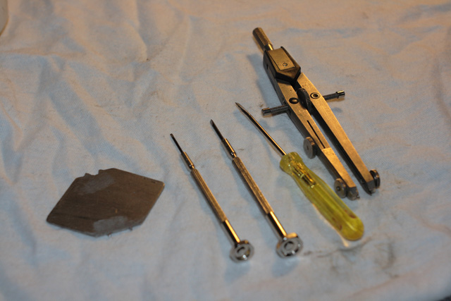
Before you start, prepare a clear worksurface and spread out a cloth to work on. It helps to prevent things rolling if you drop them. Get the tools ready and find a container or small tray for the keeping the parts safe while they're loose. I use the lid of a small biscuit tin. You'll need a jeweller's plain screwdriver about 1.2mm wide (and a small Phillips screwdriver if you're working on an SPII or F), a larger screwdriver about 3mm wide and three special tools for undoing slotted nuts and screws. I've described these later.
Firstly remove the lens and fit a body cap if you have one, and remove the battery. Set the shutter speed on B and the ASA on 100 - these are just easy-to-remember reference numbers in case you need them during re-assembly. B is the easiest setting to identify while the speed dial is removed.
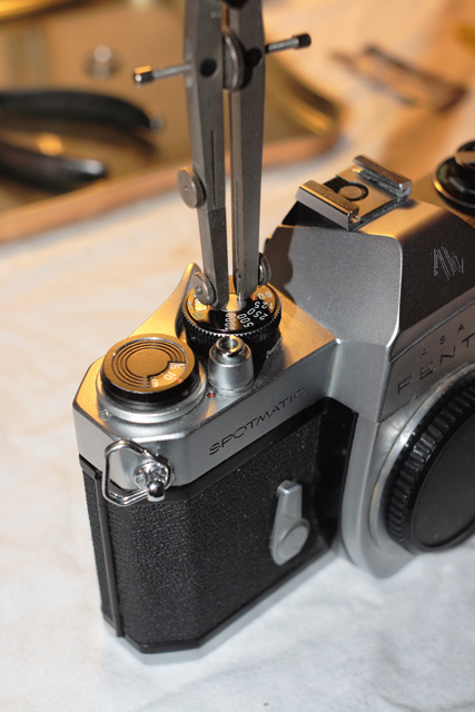
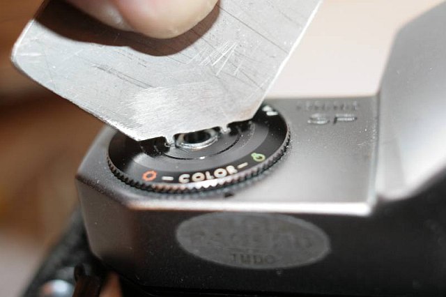
Without changing these settings, remove the small aluminium screw in the centre of the shutter speed dial. This screw is normal RH thread. You'll need to find or make a tool with two pins that fit the two small holes in the screwhead - I used a small pair of adjustable dividers with the pins ground down slightly. Be very careful not to let the tool slip and scratch the top of the screw.
Keep downward pressure on the speed dial as the screw is loosened. There's a spring underneath that will jump out and fly across the room if you're not careful!
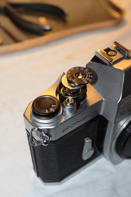
With the screw removed the speed dial and the ASA dial are released and can be removed. The spring and the body of the knob can also be lifted off. There might be a thin brass spacer washer on the top of the central shaft. If so, be careful not to lose it. The washer seems to have been omitted on later models. Don't worry about remembering the position of the dials, everything goes back only one way.
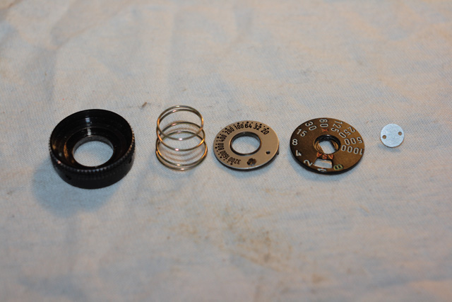
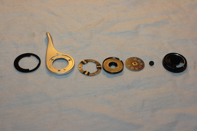
These are the components of the shutter speed/ASA knob in order of reassembly:
Now the film advance lever and frame counter. Using the small screwdriver, slacken the three tiny setscrews in the edge of the cap over the frame counter dial and lift off the cap. Make sure the setscrews aren't in any danger of becoming fully unscrewed - you'll never find one again if it falls out.
Use the larger screwdriver to undo the screw holding the frame counter dial in place. This screw is LEFT HAND thread.
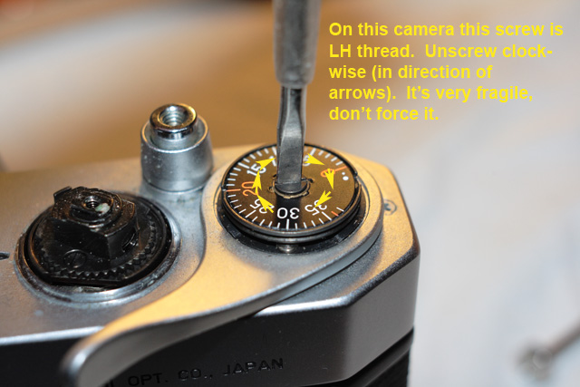
Take great care with this screw, it's very fragile and shears easily. Don't try to force it - if it won't turn one way, try the other. It doesn't need to be very tight, just the slightest amount of torque will hold the dial in place when you reassemble.
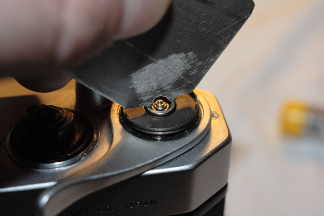
With the dial removed you'll see a slotted nut holding the base of the frame counter dial. To undo this you'll need a special tool, such as a lens ring spanner with spade ends. If you don't have one of these you can make a tool to fit. I cut a small square shape out of stainless steel sheet and formed the teeth to fit the nut with a fine file.
On earlier cameras (serial numbers up to 3,000,000) this nut is RH thread but on later cameras it was changed to LEFT HAND thread.
Under the frame counter base, the winding lever is fixed with a spring washer hooked under three bayonet wings on the central shaft.
First unscrew the three small screws fixing the washer to the lever. In this picture two of the three screws have already been removed. Now work the washer round until the bayonet wings become disengaged.
It might help to operate the lever while preventing the washer from turning. When the washer is free the winding lever can be lifted off, and then remove the plastic washer sealing the hole in the cover plate. Again, this only goes back one way.
These are the components of the winding lever and frame counter, again in order of reassembly.
TAKE NOTE: The next job is to remove the film rewind crank knob and the dials beneath it. The rewind spindle is the only way of opening the camera back and at one point it might need to pushed down inside its tube to undo the nut. If the camera back latches shut at this point it is virtually impossible to open it again! So, for safety, at this point stick some insulating tape over the latch and check that it can't close properly before you remove the knob.
Now you can safely remove the rewind knob. Prevent the spindle from turning with the larger screwdriver in the fork inside the film compartment and then unscrew the knob by hand. This is normal RH thread.
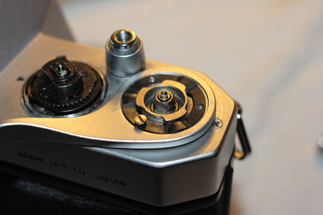
The dials beneath the rewind knob are held in place by another nut with two holes, which needs a different special tool to undo. I used the opposite corner of my piece of steel.
You might need to push the spindle down in its tube to reach the holes in this nut. Make absolutely certain the camera is open so that you can push the spindle back up again!
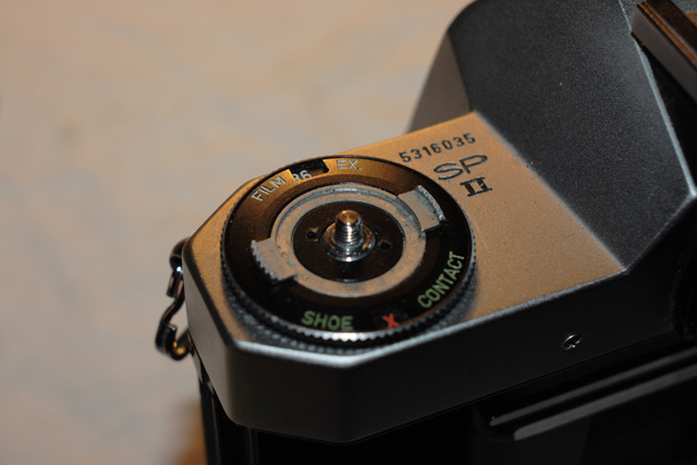
With the nut removed, all the dials can now be simply lifted off the camera. The SP, in the upper picture above, has a simple film-type reminder dial which turns through 360° and a thin spacing washer between this and the top cover. In the lower picture, the SPII and F have an aluminium ring with two wings which controls the film type and exposure reminder in the front window. The larger outer dial is a switch to select either FP or X synchronisation for the hotshoe. On these cameras there is a spring washer under the aluminium ring, but no washer under the main ring. Try to keep this complete assembly together when you lift it off as this makes it easier to reassemble, but it doesn't matter if it separates.
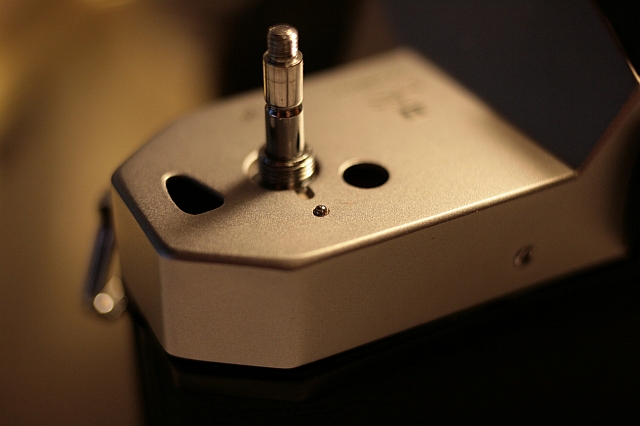
The SPII has a ball-bearing detent for the sync switch under the large dial. Thankfully there's no spring under it, but be extra careful not to lose it. A magnet is helpful here.
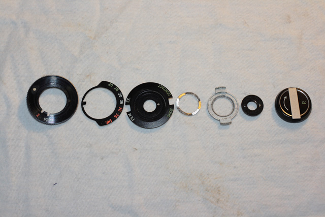
These are the components at the rewind end of the SPII, again in order of reassembly.
All that's needed now is to remove the screws fixing the cover to the main camera body. Each model has a different arrangement and number of screws, and the screws are different sizes, so take note of the type and size as you remove them. The single screw on the SP is a plain slotted type, but later models have several Phillips type screws.
With the screws removed the cover lifts straight up. Take care not to drop the loose stud inside the shutter release button, and don't forget to replace it when the cover is refitted!
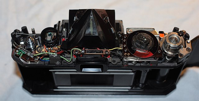
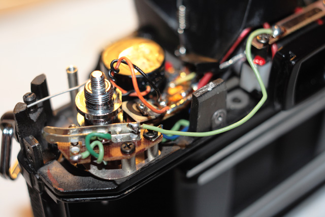
The sync switch on the SPII consists of two spring contacts which are forced together by the probe under the dial. The cover has a spring under the hotshoe which contacts with the bar above the viewfinder, top right corner in this picture. The switch, contacts and the green wires are missing on the SP.
The next stage will be the fun part, modifying the electronics and soldering the two resistors. Watch this space.
_________________
Peter - Moderator |
|
| Back to top |
|
|
zewrak

Joined: 12 Apr 2008
Posts: 1212
|
| Posted: Wed May 21, 2008 10:18 am Post subject: |
|
|
zewrak wrote:
Get going already, tomorrow my Spotmatic arrives. Excellent work!
_________________
My homepage, all manual shots |
|
| Back to top |
|
|
peterqd
Joined: 28 Feb 2007
Posts: 7448
Location: near High Wycombe, UK
Expire: 2014-01-04
|
| Posted: Fri Jan 29, 2010 10:24 am Post subject: |
|
|
peterqd wrote:
Bump
_________________
Peter - Moderator |
|
| Back to top |
|
|
Mal1905

Joined: 30 Oct 2008
Posts: 1705
Location: Dublin, Ireland
Expire: 2011-11-18
|
| Posted: Fri Jan 29, 2010 1:32 pm Post subject: |
|
|
Mal1905 wrote:
A fine bump, Peter - this is brilliantly documented work from you guys
Articles like this should be stickied, or highlighted in some other way.
_________________
Canon EOS 5D / EOS 40D
Carl Zeiss Jena: Flektogon 2.8/20, 2.4/35, 2.8/35, Pancolar 2/50, MC 1.8/50, MC 1.8/80, Triotar 4/135, Tessar 2.8/50, S 4/135 1Q, S 3.5/135, Sonnar 3.5/135 MC, 2.8/180, Biotar 2/5,8cm, 2/58, 1.5/75
Carl Zeiss: Distagon 2/28 T*, 1.4/35 T*, Ultron 1.8/50, Tessar 2.8/50, Planar 1.4/50 T* MM, 1.7/50 T* MM, 1.4/85 T* AEG, Sonnar 2.8/135 T*
Asahi Optical Co.: Super-Multi-Coated Takumar 4.5/20, 3.5/24, 3.5/28, 2/35, 3.5/35, 1.4/50, 1.8/55, 1.8/85, 2.8/105, 2.8/120, 2.5/135 I & II, 3.5/135, 4/150, 4/200, 4/300, 5.6/400, 4/45-125, 4.5/85-210, Super-Takumar 4.5/20, 3.5/24, 3.5/28, 2/35, 3.5/35, 1.4/50, 1.8/55, 2/55, 2.8/105, 3.5/135, 4/150, 4/200, 4.5/70-150, Fish-Eye-Takumar 4/17, Macro-Takumar 4/50, Super-Macro Takumar 4/50, Super-Multi-Coated Macro-Takumar 4/50, 4/100, Bellows-Takumar 4/100, Asahi-Kogaku Takumar 3.5/50, 2.4/58, 3.5/100, Asahi-Kogaku Tele-Takumar 3.5/135, Auto-Takumar 2.3/35, 3.5/35, 1.8/55, 1.8/55 (Zebra), 2/55, 2.2/55, 1.8/85, 2.8/105, 3.5/135, Takumar 4/35, 2.2/55, 2/58, 2.8/105, 3.5/135, 3.5/200, 5.6/200, Tele-Takumar 5.6/200, 6.3/300, SMC Takumar 1.4/50, 1.8/55, 2/55, SMC-M 1.4/50, 1.7/50, 2/50
Tomioka: Tominon 2/5cm, Auto-Chinon 3.5/21, 1.4/55, Auto-Yashinon DS-M 1.2/55 |
|
| Back to top |
|
|
Esox lucius

Joined: 26 Aug 2008
Posts: 2441
Location: Helsinki, Finland
Expire: 2011-11-18
|
| Posted: Fri Jan 29, 2010 1:37 pm Post subject: |
|
|
Esox lucius wrote:
| Mal1905 wrote: |
| Articles like this should be stickied, or highlighted in some other way. |
Click the rate button below the post |
|
| Back to top |
|
|
peterqd
Joined: 28 Feb 2007
Posts: 7448
Location: near High Wycombe, UK
Expire: 2014-01-04
|
| Posted: Fri Jan 29, 2010 2:49 pm Post subject: |
|
|
peterqd wrote:
| Mal1905 wrote: |
A fine bump, Peter - this is brilliantly documented work from you guys
Articles like this should be stickied, or highlighted in some other way. |
Thanks Malachy. I bumped it up for djmike to see how to remove the cover of his SPF.
I see the part about actually soldering in the new resistors isn't here on this thread (in fact I'm not sure whether if it was ever posted). I have all the pics safe, so I'll do it soon. Also the diode method in case eeyore-nl needs it!
_________________
Peter - Moderator |
|
| Back to top |
|
|
Nesster

Joined: 24 Apr 2008
Posts: 5883
Location: NJ, USA
Expire: 2014-02-20
|
| Posted: Fri Jan 29, 2010 10:56 pm Post subject: |
|
|
Nesster wrote:
Brilliant, a service to humanity, really - or at least OMists and Spotmen and women
_________________
-Jussi
Camera photos
Print Photographica
|
|
| Back to top |
|
|
Shiladitya


Joined: 31 May 2008
Posts: 306
Location: New Delhi, India
|
| Posted: Tue May 04, 2010 6:53 am Post subject: |
|
|
Shiladitya wrote:
| peterqd wrote: |
Thanks Malachy. I bumped it up for djmike to see how to remove the cover of his SPF.
I see the part about actually soldering in the new resistors isn't here on this thread (in fact I'm not sure whether if it was ever posted). I have all the pics safe, so I'll do it soon. Also the diode method in case eeyore-nl needs it! |
Peter, Did you get a chance to put together the electronic modification part? I have my second Spottie (IIa) arriving shortly and as per the owner modern batteries do not work well. So I guess I would try the mod. Thanks.
_________________
Camera: 35mm SLR: Nikon F4s, Nikon FG, FE2, FM2n, FA; Pentax K1000, Spotmatic II, MZ60; Exakta Varex IIb, Olympus OM1n;
MF TLR: Yashica Mat 124G, Yashica 635, Rolleiflex Automat MX EVS
35mm RF: Voigtlander Prominent, Yashica Electro GSN, Minolta Hi-Matic 7s
MF Folder: Agfa Isolette III
Digital: Canon 5DC, Canon 550D
Lenses: Nikkor- 2.8/55 Micro, 1.4/50 AIS, 1.2/55 AI, 2.8/24 AIS, 2.8/20 AIS, 4/200 AIS, 2.5/105 AIS
Pentax K: SMC 1.7/50, 2.8/24, 3.5/135, 4/200 & 4.5/80-200
M42: SMC Tak 1.8/55, SMC Tak 3.5/28, SMC Tak 3.5/135, Super Tak 4/200, Yasinon DX 1.7/50, Meyer Oreston 1.8/50
Zuiko: 1.8/50, 3.5/28
Exakta: Pancolar 2/50, Pentacon 3.5/30, Enna 4.5/240
Prominent: Ultron 2/50, Skoparon 3.5/35, Dynaon 4.5/100 |
|
| Back to top |
|
|
rnbc
Joined: 29 Nov 2010
Posts: 4
Location: Lisboa
|
| Posted: Mon Nov 29, 2010 8:24 pm Post subject: |
|
|
rnbc wrote:
Hello! This is my first post in this forum.
I just did the meter modification in my own Spotmatic, since the V40PX battery I was using is now quite old (but still operating). I actually did it before finding this forum...
I must stress that after calibration, but before modification, with the Silver battery the meter values at normal light levels (ISO-100 down to 1/8s or so) were accurate, only becoming inaccurate at the lowest light levels, with the meter becoming oversensitive by 2/3 EV or so at ISO-100 1s (the lowest light level it can measure).
With the mercury oxide cell the values were extremely accurate at all light levels though, so I decided I should proceed with the modification to retain that excellent performance.
Anyway, I used standard resistor values since they are quite close to what we want, and if cherry-picked they might actually result in a better meter performance than with the original mercury oxide battery. Since were I get them they only sell by the dozen (0.3€ each resistor pack) I could cherry-pick them.
I recommend reading more info about the modification in this site...
www.mypentax.com/Spotmatic_meter_mods.html
Where not only is the procedure very well detailed but there are also links for Spotmatic service manuals, explaining exactly how to disassemble and assemble the camera:
www.mypentax.com/Repair_manuals.html
www.pentax-manuals.com/manuals/service/servicemanuals.htm
I found them most illustrative to understand which wires are which and the detailed procedures gave me extra confidence to proceed.
Now, back to the modification, the values I measured in my camera where the following:
-- 2890 Ohm for the meter coil itself (not 3k as they say!)
-- 1.58V Silver Oxide battery (Renata 394, 9.5x3.6mm), mildly used (1.61V when fresh, 1.55V "nominal", but 1.57V for most of the time according to the discharge graphs in the manufacturer's site).
-- 1.36V Mercury Oxide battery (Varta V400PX), mildly used but old (1.35V nominal).
-- 463 Ohm for the cherry-picked series resistor (470 Ohm nominal).
-- 21.3 kOhm for the cherry-picked parallel resistor (22 kOhm nominal).
The modification would be accurate for (463+2890)/2890*1.36=1.578V, which is close enough to 1.58V or 1.57V in my humble opinion, since batteries are not that exact anyway.
The final meter resistance after modification is 1/(1/(463+2890)+1/21300)=2897 Ohm, instead of 2890 Ohm. This is within 0.24% of the original meter coil, much better than factory tolerances!
The meter now gives exactly the same values with the Silver cell as before with the Mercury cell, as expected anyway. I also calibrated it for about 1/5 EV overexposure, since my shutter is calibrated a bit faster also -- exactly how much varies a bit with the exact speed selected, but it's about 1/5 EV in average. That way they both tend to match, and it's much easier to calibrate the meter than the shutter.
Just a small note to say that the total current flowing through the meter circuit is a lot larger than through the coil. In fact the coil is centered at 3uA but the total current varies between 24uA (no light, meter set to 1s) and 260uA (lots of light, meter at 1s). With the needle centered, which is what matters, I measured ~60uA at low light and ~90uA with lots of light. So the circuit is close to a balanced bridge, and the current flowing through the coil is quite irrelevant. I didn't tried without it, but probably the 22 kOhm resistor is irrelevant for the modification accuracy.
PS: I calibrated the meter using the same lens in the same settings in 2 digital bodies (Sigma SD14, Canon 1000D) and the Spotmatic and comparing the readings of all 3 cameras. Modern cameras tend to agree and are very accurate, I even compared with a Nikon D700 and it came spot on.
PPS: I found how much the different speeds of the Spotmatic were "off" by using a digital camera behind the spotmatic shutter curtains (the digital with a longer exposure) and comparing the results with the digital camera's own shutter (modern shutters are extremely accurate). Just out of curiosity the values I obtained were +/- the following:
set -- measured
1 -- 1
0.5 -- 0.42
1/4 -- 1/5
1/8 -- 1/8
1/15 -- 1/15
1/30 -- 1/30
1/60 -- 1/60
1/125 -- 1/125
1/250 -- 1/250
1/500 -- 1/450
1/1000 -- 1/1000 |
|
| Back to top |
|
|
peterqd
Joined: 28 Feb 2007
Posts: 7448
Location: near High Wycombe, UK
Expire: 2014-01-04
|
| Posted: Tue Nov 30, 2010 1:19 am Post subject: |
|
|
peterqd wrote:
Thanks for this extra info! You measured the voltages and resistances a lot more accurately than me.
On my cameras I found it was not quite possible to calibrate the camera correctly using a 1.55v battery and simply adjusting the calibration resistor, but it was probably near enough that the difference in light reading would have been unnoticable. But probably every camera has slight differences in the resistance of the circuit, so this cannot be a general rule. That's why I share your view about the modification being worthwhile.
PS I fixed your links - "http:\\" should be omitted.
_________________
Peter - Moderator |
|
| Back to top |
|
|
magkelly

Joined: 06 Jul 2010
Posts: 182
|
| Posted: Tue Nov 30, 2010 2:27 am Post subject: |
|
|
magkelly wrote:
I had problems with this with my SP but I've never had any problems with using non-Weins with my SPII. I use that camera with the Energizer batteries all the time. Maybe a bit overexposed or under sometimes, but not by much. Usually it's just me doing it, not the camera. Nothing I can't attribute to user error and me being new to SLR's. It's nothing a quick trip through Camera Raw can't handle.
My only problem with using them is that no one seems to carry them locally so I have to special order them all the time from Amazon. Queenie, my SPII, seems to do just fine with the bunny batteries though. I like them better than the Wein cells myself. I kind of wish she used the LR44 clones though. They're all over the place, unlike the S387's.
I'd never try something like this. It is just way beyond me, but you guys, I am very impressed. I don't think that it's a problem with every Spottie. But for those who need an adjustment, why not? I say go for it if you can do it. |
|
| Back to top |
|
|
peterqd
Joined: 28 Feb 2007
Posts: 7448
Location: near High Wycombe, UK
Expire: 2014-01-04
|
| Posted: Tue Nov 30, 2010 10:35 am Post subject: |
|
|
peterqd wrote:
| magkelly wrote: |
I had problems with this with my SP but I've never had any problems with using non-Weins with my SPII. I use that camera with the Energizer batteries all the time. Maybe a bit overexposed or under sometimes, but not by much. Usually it's just me doing it, not the camera. Nothing I can't attribute to user error and me being new to SLR's. It's nothing a quick trip through Camera Raw can't handle.
My only problem with using them is that no one seems to carry them locally so I have to special order them all the time from Amazon. Queenie, my SPII, seems to do just fine with the bunny batteries though. I like them better than the Wein cells myself. I kind of wish she used the LR44 clones though. They're all over the place, unlike the S387's.
I'd never try something like this. It is just way beyond me, but you guys, I am very impressed. I don't think that it's a problem with every Spottie. But for those who need an adjustment, why not? I say go for it if you can do it. |
Thanks. LR44 batteries are the alkali type and I'd advise not using these on a Spotmatic SP or SPII. The cameras were designed to use mercury batteries, which had a very steady voltage output over their lifetime. The output of alkali batteries reduces steadily over their lifetime, starting at maybe 1.6 or 1.7 when they're new and reducing to maybe 1.2 or even lower. This isn't vital with more modern cameras designed to cope with voltage drop (including the SPF), but the meter needles on the earlier models will reflect this. Silver oxide cells hold a much steadier voltage, almost as good as mercury.
_________________
Peter - Moderator |
|
| Back to top |
|
|
rnbc
Joined: 29 Nov 2010
Posts: 4
Location: Lisboa
|
| Posted: Wed Dec 01, 2010 3:21 am Post subject: |
|
|
rnbc wrote:
peterqd, as you said it's not possible to correctly calibrate the meter for 1.57V before the modification, but the difference at high and medium light levels is so low as to be meaningless. The real problem starts at low light levels, where it becomes oversensitive, and is compounded with the fact that film starts to have reciprocity failure at 1/4s or so... not a good prospect. You end up with underexposed negatives.
I find the meter is a lot more accurate than shutter speeds. BTW, my shutter is correctly calibrated, since you calibrate at 1s, 1/60 and 1/1000, with other speeds supposedly "falling in". Despite that some intermediate low speeds are shorter by almost 1/3 EV, as you can see in the table, and one of the high speeds is a bit lazy. Anyway, by factory specs the meter and shutter only have to match each other better than 1/2 EV over the whole range, so mine is officially approved, so to say We must not demand to much accuracy from these old beasts
magkelly, the modification is easy, the real problem is disassembling/assembling the camera. Some tools are also not readily available: I used a modified (sharpened) needle-nose pliers and a caliper as tools... but I think if you study the manuals you won't have much trouble. Just don't try it before you understand exactly what you are doing!
Apart from the fact a LR44 has a sloping discharge curve I don't think a SR44 (silver oxide LR44) will fit the Spotmatic's compartment: it's 11.6 x 5.4 mm while the original battery is 9.5 x 3.6 mm (plus plastic gasket, but only around the top, not on the bottom). The closer you can get is, of course, the 387S, but I never saw them for sale over here. Otherwise a SR936 (AG9, Renata 394...) will do, since it's the same battery minus the gasket. To avoid a short circuit, which is what the gasket does, I recommend isolating the interior of the battery compartment (except for the + contact and the metallic lid) with a bit of tape. Also be careful when you start to screw in the lid to avoid short-circuiting the battery: check the battery is leveled, and put the lid leveled from the beginning.
A smaller cell will also work, albeit with some rubber ring to center it, and since the meter uses so little energy will probably last for the same time: cell self-discharge is probably more important than meter drain. For example, the cell I mentioned is 84mAh and will take 4 months to discharge (in the dark) even if you forget to shut down the meter, and 13 days under maximum the maximum consumption I could measure. If you don't forget the meter switched on, it would probably last >10 years, except it will self-discharge before. |
|
| Back to top |
|
|
magkelly
Joined: 06 Jul 2010
Posts: 182
|
| Posted: Wed Dec 01, 2010 4:12 am Post subject: |
|
|
magkelly wrote:
I use the 387S from Energizer. Fits perfectly, no ring needed, and works just fine. LR44's are too big for Spotmatics. |
|
| Back to top |
|
|
peterqd
Joined: 28 Feb 2007
Posts: 7448
Location: near High Wycombe, UK
Expire: 2014-01-04
|
| Posted: Wed Dec 01, 2010 1:50 pm Post subject: |
|
|
peterqd wrote:
| rnbc wrote: |
| The closer you can get is, of course, the 387S, but I never saw them for sale over here. |
I bought mine from this seller in USA. The postage is so cheap and quick that it doesn't make a lot of difference from buying from EU.
Click here to see on Ebay
_________________
Peter - Moderator |
|
| Back to top |
|
|
graffixjones
Joined: 14 Feb 2022
Posts: 1
|
| Posted: Mon Feb 14, 2022 1:57 am Post subject: |
|
|
graffixjones wrote:
I realize this is necro’ing an old thread, but I wanted to thank you guys if you happen to still be around. I found some Vishay resistors on eBay rated at 442ohm 1/8 watt 1%, and 23.2K 1/4 watt 1%. That was close enough for me. Mounting the resistors was a fun experience, and I ended up using their legs and soldered them in “ugly bug†style, with one bridging across the circuit board, and one branching off the board and then connecting to the red lead for the galvanometer.
I converted two Spotmatic SPs, and while I haven’t ran any film through them since the conversion, they’re responding to light just like they did prior to the conversion. I take that as a good sign. The meter seems to be more sensitive in the lower range, but I’ll know once I get a couple rolls of film through each of them.
I’m just getting back into B&W film after 20 years of shooting digital, so I’m getting all this old gear back into shape. Threads like this have been a godsend, even 10+ years after the last reply was posted.
Thanks again. |
|
| Back to top |
|
|
|
|