thundertwin72

Joined: 28 Sep 2011
Posts: 43
Location: Barcelona
Expire: 2013-12-16
|
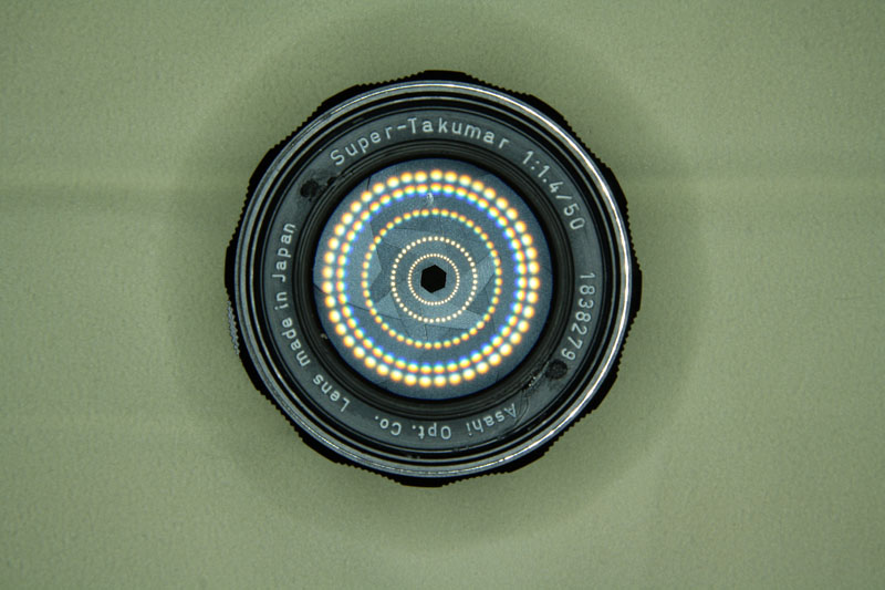
 Posted: Fri Dec 14, 2012 10:38 pm Post subject: Super-Takumar 1.4/50 dissasembly. Posted: Fri Dec 14, 2012 10:38 pm Post subject: Super-Takumar 1.4/50 dissasembly. |
 |
|
thundertwin72 wrote:
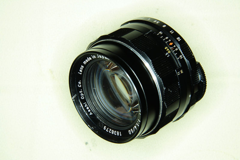
A few days ago, knowing I had some problems (focus and aperture), I bought it from a fellow from another forum in hopes of getting it back. Since the focusing system is similar in most lenses, comment, as a guide, now the process. I apologize for the translation: I do not speak English and I used Google Translator.
Unscrew (while pressed) the front trim ring. If you do not have a specific tool for it, a rubber drain plug can serve.
Then, removing the three smaller screws, we can remove the ring with thread holder.
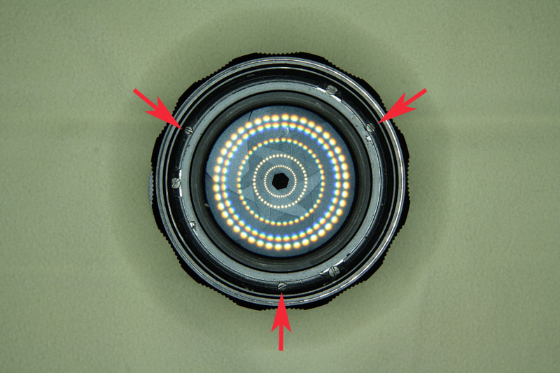
To remove the focus ring, we'll remove the three screws on the back burner.
Those at first, fix the headlights and diaphragm to helicoid.
After removing the focus ring, there was a recess in it, which corresponds to the path it takes to rotate. The ends of said recess with a screw cap will be seen later that in accordance advance disassembly.
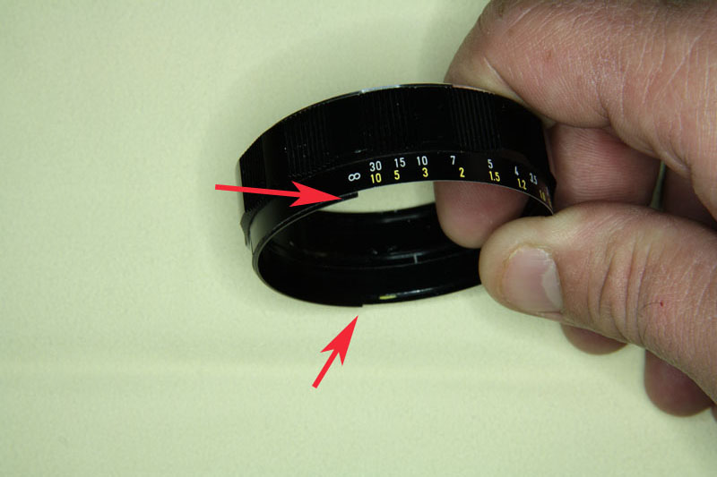
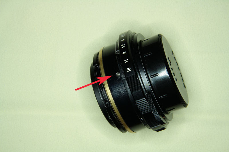
Mark with a permanent ink pen (with alcohol can then delete) the position of the rim with the inscriptions of depth of field, loosen the three set screws that are around and extract.

Now we can see the screw abuts the focusing ring recess, limiting its travel, does not require disposal.
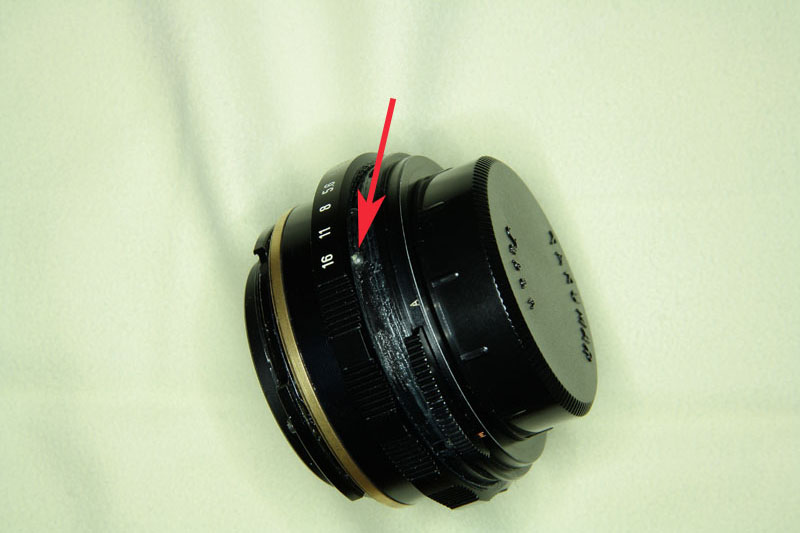
At the height of the screw, and after the aperture ring, is the steel ball that allows the "click" to diafragmar.
Pulling slowly aperture ring, see the aforementioned ball, you have to be careful because she can jump and lost. Remove the ring.
Now we must remove the back cover, which contains mechanisms and frame stopped down. This will mark the first position, we will remove the three screws around, and she'll pull gently.
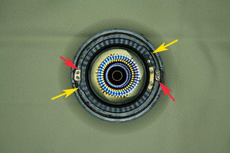
We now note inside the lid removed and we pay attention to two points:
On the right, the cam pin which connects the rear of the objective diaphragm lever and whose end is shaped fork.
And at the left, where that pivots the shaft fixed with a screw.
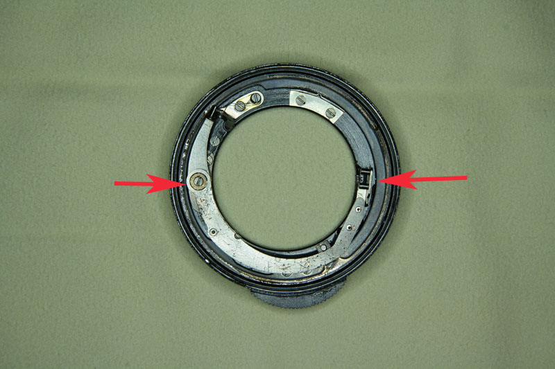
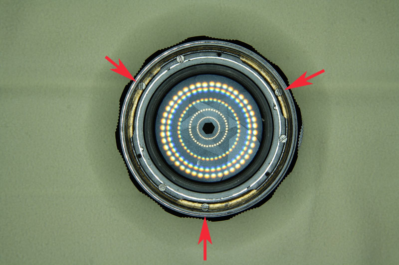
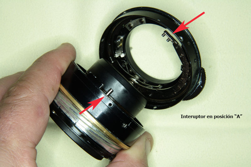
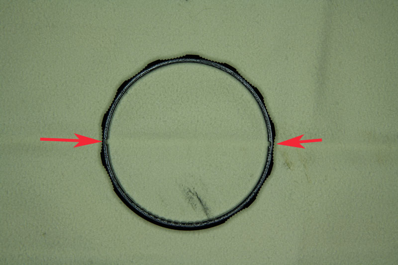
When we return to riding, we must take into account the points mentioned in the previous step, the cradle of the diaphragm cam and the pivot of it, must match in two recesses marked with yellow arrows. On the right, larger, corresponding to the fork. The left, smaller, the pivot. If mounted upside down, the diaphragm mechanism will not work.
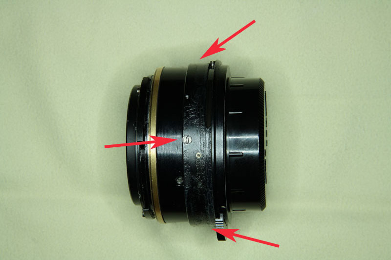
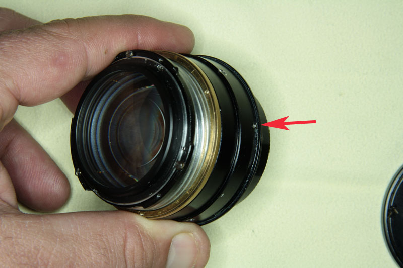
Red arrows indicated with and fixed by a pair of screws, plates appreciate that guide and limit the travel of approach; mark in which each side is (are different and if installed incorrectly interfere with the movement of the aperture setting mechanism) and withdrawal.
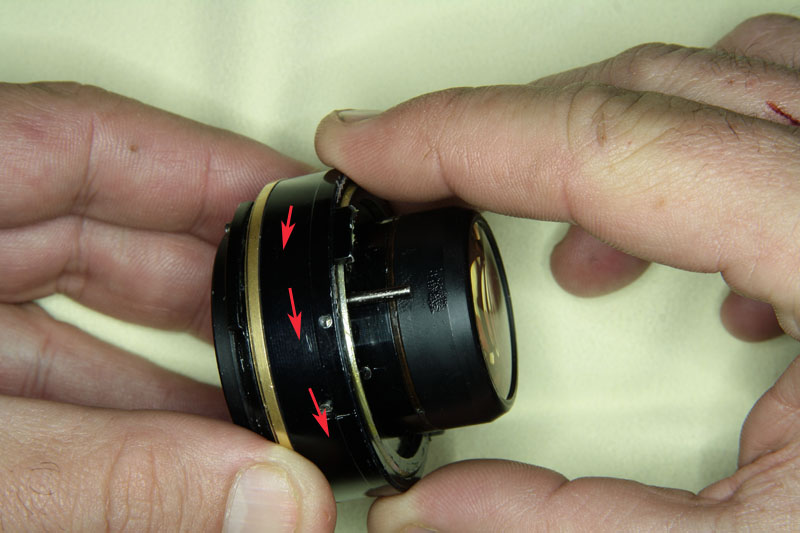
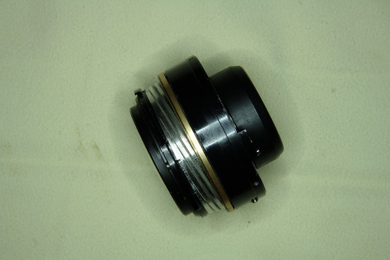
Holding the brass ring do? where is the focusing screw, screw in the direction indicated by the arrows (contrary thread will), the black color ring until it stops (1/4 turn more or less). Caution: Do not tighten too hard or you can get stuck in a way that is very difficult to undo later.
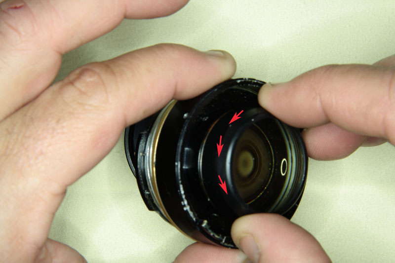
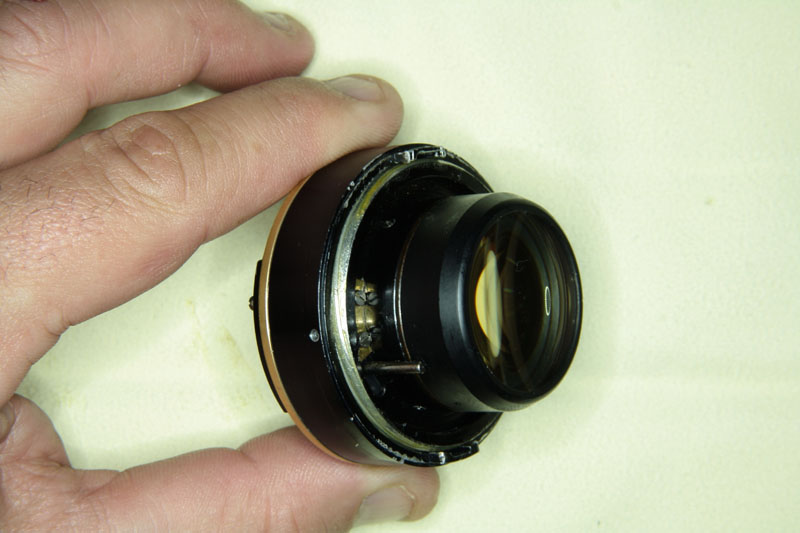
Now, holding the black ring unscrew in the direction indicated by the arrows, the light clusters forming block, diaphragm and helical. Do it very slowly and check (very important) the exit point of the thread.
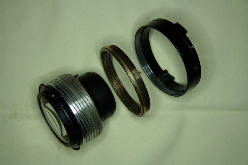
Unscrew, as indicated by arrows, brass ring and black ring (the call because I do not know how they are called).
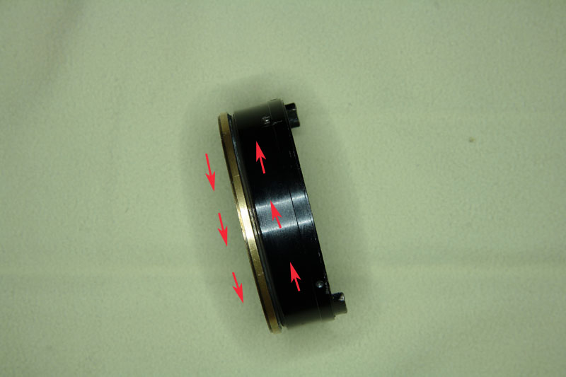
This image shows the three parts making up the focusing mechanism. Each one is threaded into the next and is the intermediate ring with which makes rotation, when mounted, the focus is shifting.
Clean with petrol lighter all traces of grease and / or dirt and re-lubricate sparingly.
I personally use for finer threads, a grease like this: Quilube , is rather smooth. For thicker threads: a thicker grease.
Yet greased and reverse the process and remount all:
first screw until it stops brass rings and black. For the starting point, turn to screw the front block, also until it stops.
Holding back the brass ring, unscrew the black ring about 1/4 turn (remember that going from right to left) until the match accommodations abutting badges with their guides. Screw them in place.
To the rear of approach does not interfere with the movement of the aperture setting mechanism, we turn the brass ring to eject the helicoid.
Riding back cover hours considering diaphragm lever (lower), has to stay in the fork (top) of the cam pin that connects the rear. Mount and tighten.
On both sides of the objectives there guides which delimit the extent of the aperture, which are traversed by respective screws (shown only one shown).
Said screws fit into respective recesses having aperture ring so that, when rotated, moving the screws by guides.
With a little fat, place the steel ball into its housing and pushing it around with the tip of a screwdriver, set the aperture ring.
Replace and tighten the ring with the depth of field scales.
With the lens mounted on a camera and turning the brass ring, focus on a distant object to calibrate infinity.
After that and without touching anything, placing the focus ring so it stops when matching orange diamond (index distances), with the infinity position. Care that nothing moves, screw.
Place and screw the threaded ring with the filter holder and, after this, screw the trim ring.
If care has been taken back to have a lens whose focus is smooth and fluid.
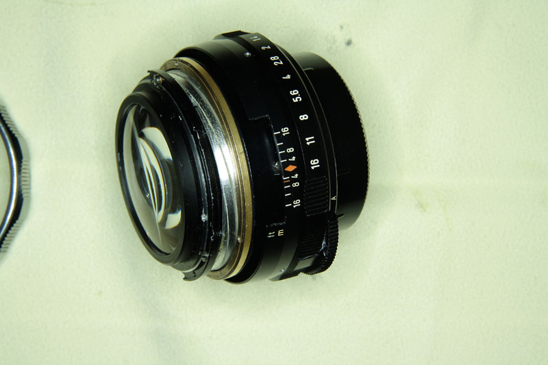
In the picture: the lens at infinity position.
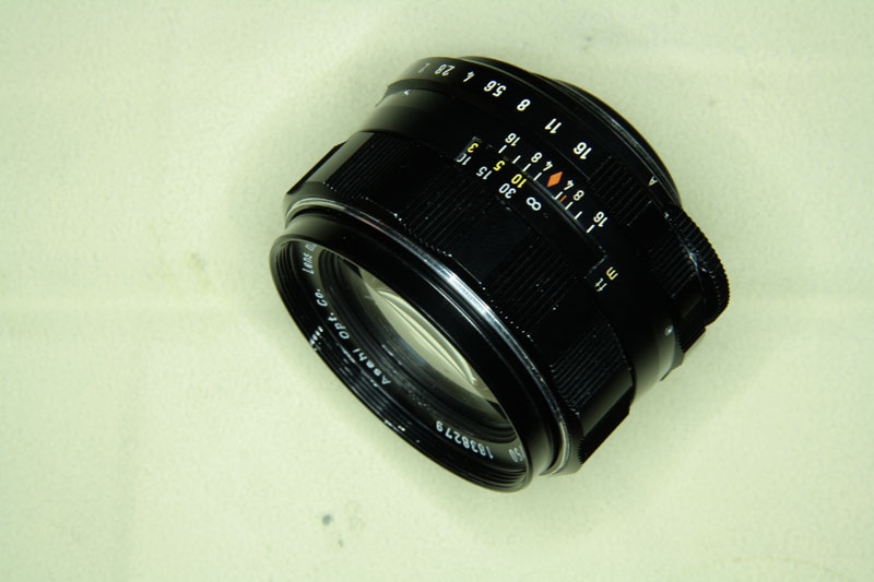
And now in a position minimum focus distance.
Note: The holes in the front of its previous owner.
Regards.
Jordi.
_________________
DSLR: Canon 50D, Canon 1000D.
EVIL: Olympus e-pl1, Fuji X-E1.
SLR: Fujica ST801, Praktica MTL5B, Praktica MTL50, Pentax MX, Pentax ME Super, Pentax K1000, Canon A1, Canon AE1 Program, Canon T60, Canon EF, Canon FTb QL, Minolta SRT-101, Minolta XG9, Nikon FE2, Nikon FM2n, Nikon FM, Nikon FE, Nikon FA, Olympus OM-1, Olympus OM-10, Yashica FX-3, Yashica FX-3 Super 2000, Contax 137MA Quartz, Contax RTS, Zenit E, Zenit EM, Зенит ET, Contaflex II, Contaflex IV, Киев 60 TTL.
Rangefinder: ФЗД-2, Зоркий-4, Киев-4.
Rangefinder fixed lens: Yashica Electro GSN, Yashica Electro GX, Yashica Minister D, Yashica Lynx 14E, Yashica Lynx 5000E, Canonet QL17, Olympus 35RC.
TLR: Flexaret II Flexaret IIa, Flexaret IIIa, Flexaret IV, Flexaret IVa, Flexaret Va, Flexaret VI Automat, Flexaret VIa Automat, Flexaret Standard, Flexaret VII Automat, Weltaflex, Rolleicord Va, Yashica Mat 124G.
LENSES:
(m42): Chinon 2.5/24, Super Takumar 3.5/28, Pentacon 2.8/29, Pentacon 3.5/30, Chinon Auto 2.8/35, Super Takumar 1.4/50, SMC Takumar 1.4/50,EBC Fujinon 1.4/50, Pentacon 1.8/50, EBC Fujinon 1.8/55, Helios 44-2 2/58, Helios 44M 2/58, Helios-44M4 2/58, Vivitar Series 1 2.5/90, Pentacon 2.8/135, CZJ Sonnar 3.5/135, MC Юпитер-37AM 3.5/135, Kenlock 4/200, Jupiter-21M 4.5/200.
(PK): SMC Pentax-M 1.4/50, SMC Pentax-M 1.7/50, SMC Pentax-A 1.7/50, Kiron 2.8/105.
(C/Y): Yashica ML 1.9/50, Yashica ML 1.7/50, Vivitar 2.8/28, Panagor 2.8/90, Zeiss Planar *T 1.4/50, Zeiss Planar *T 1.7/50.
(FD): Soligor 2.5/28, Canon FD 1.4/50, Canon FD 1.4/50 SSC, Canon FDn 1.4/50, Canon FD 1.8/50 SC, Canon FDn 1.8/50, Vivitar 2.8/55.
(MD): Rokkor PF 1.7/50, Rokkor MD 1.7/50.
(F): Nikkor AI-S 2/35, Nikkor AI 2.8/35, Nikkor AI 1.4/50, Nikkor AI-S 1.4/50, Nikkor AI-S 1.8/50 "Long Nose", Nikkor AI-S 1.8/50, E Series 1.8/50, Nikkor AI 2/50, МС Гелиос-81Н 2/50, Panagor 3/55, Hoya 2.8/135, Hoya 3.5/35-105.
(OM): Zuiko Auto-S 1.8/50.
(Konica AR):Hexanon 1.8/40.
(Pentacon Six): MC Волна-3 2.8/80.
(LTM): Юпитер-8 2/50, И-26м 2,8/52.
(Contax/Kiev): Юпитер-8М f2/5cm.
|
|
thundertwin72
Joined: 28 Sep 2011
Posts: 43
Location: Barcelona
Expire: 2013-12-16
|
| Posted: Fri Dec 14, 2012 11:33 pm Post subject: |
|
|
thundertwin72 wrote:
| Lloydy wrote: |
Excellent, very clear and concise.  |
| hoanpham wrote: |
Thank you.
Excellent instructions. |
I appreciate your comments 
Regards.
_________________
DSLR: Canon 50D, Canon 1000D.
EVIL: Olympus e-pl1, Fuji X-E1.
SLR: Fujica ST801, Praktica MTL5B, Praktica MTL50, Pentax MX, Pentax ME Super, Pentax K1000, Canon A1, Canon AE1 Program, Canon T60, Canon EF, Canon FTb QL, Minolta SRT-101, Minolta XG9, Nikon FE2, Nikon FM2n, Nikon FM, Nikon FE, Nikon FA, Olympus OM-1, Olympus OM-10, Yashica FX-3, Yashica FX-3 Super 2000, Contax 137MA Quartz, Contax RTS, Zenit E, Zenit EM, Зенит ET, Contaflex II, Contaflex IV, Киев 60 TTL.
Rangefinder: ФЗД-2, Зоркий-4, Киев-4.
Rangefinder fixed lens: Yashica Electro GSN, Yashica Electro GX, Yashica Minister D, Yashica Lynx 14E, Yashica Lynx 5000E, Canonet QL17, Olympus 35RC.
TLR: Flexaret II Flexaret IIa, Flexaret IIIa, Flexaret IV, Flexaret IVa, Flexaret Va, Flexaret VI Automat, Flexaret VIa Automat, Flexaret Standard, Flexaret VII Automat, Weltaflex, Rolleicord Va, Yashica Mat 124G.
LENSES:
(m42): Chinon 2.5/24, Super Takumar 3.5/28, Pentacon 2.8/29, Pentacon 3.5/30, Chinon Auto 2.8/35, Super Takumar 1.4/50, SMC Takumar 1.4/50,EBC Fujinon 1.4/50, Pentacon 1.8/50, EBC Fujinon 1.8/55, Helios 44-2 2/58, Helios 44M 2/58, Helios-44M4 2/58, Vivitar Series 1 2.5/90, Pentacon 2.8/135, CZJ Sonnar 3.5/135, MC Юпитер-37AM 3.5/135, Kenlock 4/200, Jupiter-21M 4.5/200.
(PK): SMC Pentax-M 1.4/50, SMC Pentax-M 1.7/50, SMC Pentax-A 1.7/50, Kiron 2.8/105.
(C/Y): Yashica ML 1.9/50, Yashica ML 1.7/50, Vivitar 2.8/28, Panagor 2.8/90, Zeiss Planar *T 1.4/50, Zeiss Planar *T 1.7/50.
(FD): Soligor 2.5/28, Canon FD 1.4/50, Canon FD 1.4/50 SSC, Canon FDn 1.4/50, Canon FD 1.8/50 SC, Canon FDn 1.8/50, Vivitar 2.8/55.
(MD): Rokkor PF 1.7/50, Rokkor MD 1.7/50.
(F): Nikkor AI-S 2/35, Nikkor AI 2.8/35, Nikkor AI 1.4/50, Nikkor AI-S 1.4/50, Nikkor AI-S 1.8/50 "Long Nose", Nikkor AI-S 1.8/50, E Series 1.8/50, Nikkor AI 2/50, МС Гелиос-81Н 2/50, Panagor 3/55, Hoya 2.8/135, Hoya 3.5/35-105.
(OM): Zuiko Auto-S 1.8/50.
(Konica AR):Hexanon 1.8/40.
(Pentacon Six): MC Волна-3 2.8/80.
(LTM): Юпитер-8 2/50, И-26м 2,8/52.
(Contax/Kiev): Юпитер-8М f2/5cm.
|
|