| View previous topic :: View next topic |
| Author |
Message |
lucca1x

Joined: 09 Feb 2014
Posts: 93
Location: Romania
|
 Posted: Tue Dec 06, 2016 12:32 pm Post subject: DIY mini macrostage with raspberry pi and cd-rom stepper Posted: Tue Dec 06, 2016 12:32 pm Post subject: DIY mini macrostage with raspberry pi and cd-rom stepper |
 |
|
lucca1x wrote:
This topic is a follow up of a discussion here:
http://forum.mflenses.com/viewtopic.php?t=76325&sid=49f653cb79e12b0dbafa8c8091b85ab1
As I mentioned in the above topic this project it is not my design, I've just adjusted a few online resources to my purpose.
This is not a full tutorial but more of a guide. Also : DO IT AT YOUR OWN RISK.
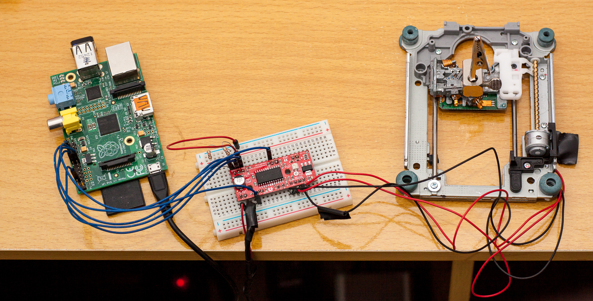
My setup looks like that:

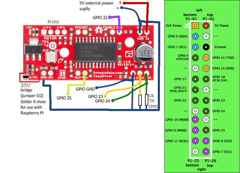
The hardware diagram:

The camera uses the usb connection on raspberry pi.
Online resources used:
http://makeitgeek.blogspot.ro/2012/12/controlling-stepper-with-raspberrypi.html (main source for hardware setup and code -- credits to the article author)
http://www.schmalzhaus.com/EasyDriver/
https://projects.drogon.net/raspberry-pi/wiringpi/download-and-install/
http://www.instructables.com/id/Raspberry-Pi-photo-booth-controller/step2/Connect-the-Camera/ (the part about gphoto2 install; Raspbian repository package didn't work for me, this tutorial did )
http://www.gphoto.org/ (for list of supported cameras, commands and options)
Materials:
- Raspberry Pi 1 model B + sdcard > 4GB . I guess any Raspberry PI model will do. you'll have to conform to the specs/pinout of other models / versions.
- Easy Driver from Sparkfun . I've already had this one laying arround. Other stepper motor drivers could be used adapting everything to their specs.
- Old but working CD-ROM drive. There are lots of old IDE drives incompatible with modern PC mainboards.
- some system to place the subject on to the stage. I'm using some helping hands.
- Breadoard
- 2x 1 Kohm resistor ( ceramic type ). I think it will work without them but is safer to protect the raspberry's GPIO
- some male-female breadboard friendly wires (arround 15-17 pc.)
- soldering iron and solder (I use a low power soldering iron arround 30W to avoid burning things)
- 2x DC 5V 1A-2A power supplies. One is for raspberry and the other one is for the driver and motor. I use 2 old 5v 1A switching power supplies. Some say 1A it is not enough for raspberry nor for driver + motor. They work for me.
The code is a executable shell script and it looks like this (for now):
| Code: |
#!/bin/sh
pause=0.0001
pause2=0.0001
pauseaftereachpicture=7
#numberofpic=$1
#stepsbetweenpics=$2
numberofpic=35
stepsbetweenpics=2
#gpio 25 ms1
#gpio 22 ms2
#ms1 ms2 resolution
#0 0 full
#1 0 half
#0 1 quarter
#1 1 eight
gpio -g mode 22 out
gpio -g mode 23 out
gpio -g mode 24 out
gpio -g mode 25 out
echo $numberofpic
echo $stepsbetweenpics
for i in $(seq 1); do
echo round $i starts:
sleep 2
gpio -g write 25 1
gpio -g write 22 1
gpio -g write 24 1
for i in $(seq $numberofpic); do
echo captura picture: $i
gphoto2 --capture-image
sleep $pauseaftereachpicture
for q in $(seq $stepsbetweenpics); do
echo picture: $i step: $q
gpio -g write 23 1
sleep $pause
gpio -g write 23 0
sleep $pause
done
done
sleep 1
gpio -g write 25 0
gpio -g write 22 0
gpio -g write 24 0
returnsteps=$((($numberofpic * $stepsbetweenpics) / 8))
for i in $(seq $returnsteps); do
ri=$(($returnsteps - $i + 1))
echo $ri
gpio -g write 23 1
sleep $pause2
gpio -g write 23 0
sleep $pause2
done
done |
The variables names are to long; I've translated them in english to be intuitive; It will be better to change them in someting shorter. A cleaner code nicely commented would be better ...
Some observations:
- don't forget to solder the 3/5V jumper on Easy Driver. It must use the logical voltage of Raspberry Pi that's 3V3
- the hardware connections must be perfect. A motor wire disconnected while the easy driver is powered on will burn it
- check the circuit for short.
- don't remove or add wires while any component is powered
- when soldering the wires to the motor pins don't remove the original ribbon cable. Solder over it and insulate the end of the cable.
- the setup is slow compared to low-level controllers, but if you use a flash the raspberry will have to wait for it to recycle anyway. My Nissin recycle time is about 5-7 sec. so the script and motor speed are not crucial.
-don't forget to connect your camera via usb to raspberry pi and check the standby time. If camera is in standby gphoto2 will return errors.
This is more of a toy, it is far from the professional solutions on the market, but is cheap and fun to play with. I've decided it's worth a try. You make your own decision  |
|
| Back to top |
|
 |
lucca1x
Joined: 09 Feb 2014
Posts: 93
Location: Romania
|
| Posted: Fri May 12, 2017 5:40 am Post subject: |
|
|
lucca1x wrote:
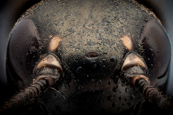
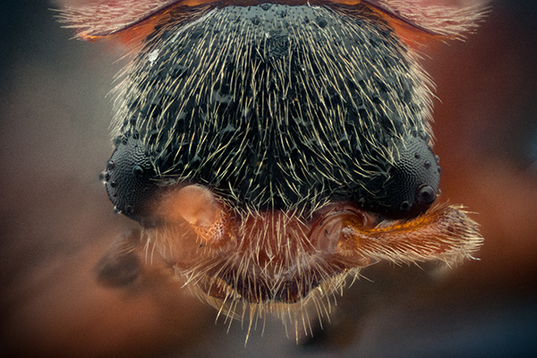
I had some spare time and took 2 stacks with this. Here are some downsized results (originals are 15 megapixels):
#1

#2
 |
|
| Back to top |
|
|
kds315*


Joined: 12 Mar 2008
Posts: 16544
Location: Weinheim, Germany
Expire: 2021-03-09
|
| Posted: Fri May 12, 2017 5:57 am Post subject: |
|
|
kds315* wrote:
Impressive, looks good! I lift my hat that you made this!! 
I simply bought a StackShot a while ago and used it a few times, but haven't done much with it.
https://www.cognisys-inc.com/products/stackshot/stackshot.php
Friend of mine now makes a high resolution stacker, less 1 micron resolution!
http://www.stonemaster.eu/products/stackmaster
Also has some easy to use software for it made.
_________________
Klaus - Admin
"S'il vient a point, me souviendra" [Thomas Bohier (1460-1523)]
http://www.macrolenses.de for macro and special lens info
http://www.pbase.com/kds315/uv_photos for UV Images and lens/filter info
https://www.flickr.com/photos/kds315/albums my albums using various lenses
http://photographyoftheinvisibleworld.blogspot.com/ my UV BLOG
http://www.travelmeetsfood.com/blog Food + Travel BLOG
https://galeriafotografia.com Architecture + Drone photography
Currently most FAV lens(es):
X80QF f3.2/80mm
Hypergon f11/26mm
ELCAN UV f5.6/52mm
Zeiss UV-Planar f4/60mm
Zeiss UV-Planar f2/62mm
Lomo Уфар-12 f2.5/41mm
Lomo Зуфар-2 f4.0/350mm
Lomo ZIKAR-1A f1.2/100mm
Nikon UV Nikkor f4.5/105mm
Zeiss UV-Sonnar f4.3/105mm
CERCO UV-VIS-NIR f1.8/45mm
CERCO UV-VIS-NIR f4.1/94mm
CERCO UV-VIS-NIR f2.8/100mm
Steinheil Quarzobjektiv f1.8/50mm
Pentax Quartz Takumar f3.5/85mm
Carl Zeiss Jena UV-Objektiv f4/60mm
NYE OPTICAL Lyman-Alpha II f1.1/90mm
NYE OPTICAL Lyman-Alpha I f2.8/200mm
COASTAL OPTICS f4/60mm UV-VIS-IR Apo
COASTAL OPTICS f4.5/105mm UV-Micro-Apo
Pentax Ultra-Achromatic Takumar f4.5/85mm
Pentax Ultra-Achromatic Takumar f5.6/300mm
Rodenstock UV-Rodagon f5.6/60mm + 105mm + 150mm
|
|
| Back to top |
|
|
lucca1x
Joined: 09 Feb 2014
Posts: 93
Location: Romania
|
| Posted: Fri May 12, 2017 7:48 am Post subject: |
|
|
lucca1x wrote:
Thanks Klaus !
It seems that the rather flimsy setup did what it had to do.
As a note: the stack was shot with nikon cfi e plan 10x wd 7.0 used at ~5:1 ratio with Nikkor 105/2.5 Ais as a tube lens (DIY adapter for the CFI lens). Subject size: ~3-4 mm. Using Kiron 105 as a tube lens the results were softer (diffraction maybe?). |
|
| Back to top |
|
|
hoanpham
Joined: 31 Jan 2011
Posts: 2575
Expire: 2015-01-18
|
| Posted: Fri May 12, 2017 9:00 am Post subject: |
|
|
hoanpham wrote:
Awesome.
I have in my plan to make one of these, and a drop rigg as well.
I use mostly Arduino. |
|
| Back to top |
|
|
kds315*
Joined: 12 Mar 2008
Posts: 16544
Location: Weinheim, Germany
Expire: 2021-03-09
|
| Posted: Fri May 12, 2017 9:16 am Post subject: |
|
|
kds315* wrote:
| lucca1x wrote: |
Thanks Klaus !
It seems that the rather flimsy setup did what it had to do.
As a note: the stack was shot with nikon cfi e plan 10x wd 7.0 used at ~5:1 ratio with Nikkor 105/2.5 Ais as a tube lens (DIY adapter for the CFI lens). Subject size: ~3-4 mm. Using Kiron 105 as a tube lens the results were softer (diffraction maybe?). |
Surprising that the Kiron delivered softer results? Ideally a 200mm lens should be used, as this is the ideal tube length for infinity objectives. Also the cheap(er) Raynox DCR-250 achromatic diopter is very good as such a lens. Bit tricky to mount, but my friend sells a special adapter for it.
_________________
Klaus - Admin
"S'il vient a point, me souviendra" [Thomas Bohier (1460-1523)]
http://www.macrolenses.de for macro and special lens info
http://www.pbase.com/kds315/uv_photos for UV Images and lens/filter info
https://www.flickr.com/photos/kds315/albums my albums using various lenses
http://photographyoftheinvisibleworld.blogspot.com/ my UV BLOG
http://www.travelmeetsfood.com/blog Food + Travel BLOG
https://galeriafotografia.com Architecture + Drone photography
Currently most FAV lens(es):
X80QF f3.2/80mm
Hypergon f11/26mm
ELCAN UV f5.6/52mm
Zeiss UV-Planar f4/60mm
Zeiss UV-Planar f2/62mm
Lomo Уфар-12 f2.5/41mm
Lomo Зуфар-2 f4.0/350mm
Lomo ZIKAR-1A f1.2/100mm
Nikon UV Nikkor f4.5/105mm
Zeiss UV-Sonnar f4.3/105mm
CERCO UV-VIS-NIR f1.8/45mm
CERCO UV-VIS-NIR f4.1/94mm
CERCO UV-VIS-NIR f2.8/100mm
Steinheil Quarzobjektiv f1.8/50mm
Pentax Quartz Takumar f3.5/85mm
Carl Zeiss Jena UV-Objektiv f4/60mm
NYE OPTICAL Lyman-Alpha II f1.1/90mm
NYE OPTICAL Lyman-Alpha I f2.8/200mm
COASTAL OPTICS f4/60mm UV-VIS-IR Apo
COASTAL OPTICS f4.5/105mm UV-Micro-Apo
Pentax Ultra-Achromatic Takumar f4.5/85mm
Pentax Ultra-Achromatic Takumar f5.6/300mm
Rodenstock UV-Rodagon f5.6/60mm + 105mm + 150mm
|
|
| Back to top |
|
|
lucca1x
Joined: 09 Feb 2014
Posts: 93
Location: Romania
|
| Posted: Fri May 12, 2017 10:29 am Post subject: |
|
|
lucca1x wrote:
Indeed a 200mm tube should be used, but it comes with 10:1 ratio, this mean under ~2mm subject size ... I'm more comfortable with 5:1 ratio.
This was taken with Kiron as tube lens:

I know is to small to judge the sharpness...
It is also said the dedicated macro lenses are not great as tube lenses, perhaps the recessed front element has something to do with it. |
|
| Back to top |
|
|
visualopsins

Joined: 05 Mar 2009
Posts: 10543
Location: California
Expire: 2025-04-11
|
| Posted: Fri May 12, 2017 4:10 pm Post subject: |
|
|
visualopsins wrote:
Thanks for sharing your work -- your first post can be used as a form for any rp project! The toys that can be made...
_________________
☮☮☮☮☮☮☮☮☮☮☮☮☮☮☮☮☮☮☮☮☮☮☮☮☮☮☮☮☮☮☮☮ like attracts like! ☮☮☮☮☮☮☮☮☮☮☮☮☮☮☮☮☮☮☮☮☮☮☮☮☮☮☮☮☮☮☮☮
Cameras: Sony ILCE-7RM2, Spotmatics II, F, and ESII, Nikon P4
Lenses:
M42 Asahi Optical Co., Takumar 1:4 f=35mm, 1:2 f=58mm (Sonnar), 1:2.4 f=58mm (Heliar), 1:2.2 f=55mm (Gaussian), 1:2.8 f=105mm (Model I), 1:2.8/105 (Model II), 1:5.6/200, Tele-Takumar 1:5.6/200, 1:6.3/300, Macro-Takumar 1:4/50, Auto-Takumar 1:2.3 f=35, 1:1.8 f=55mm, 1:2.2 f=55mm, Super-TAKUMAR 1:3.5/28 (fat), 1:2/35 (Fat), 1:1.4/50 (8-element), Super-Multi-Coated Fisheye-TAKUMAR 1:4/17, Super-Multi-Coated TAKUMAR 1:4.5/20, 1:3.5/24, 1:3.5/28, 1:2/35, 1:3.5/35, 1:1.8/85, 1:1.9/85 1:2.8/105, 1:3.5/135, 1:2.5/135 (II), 1:4/150, 1:4/200, 1:4/300, 1:4.5/500, Super-Multi-Coated Macro-TAKUMAR 1:4/50, 1:4/100, Super-Multi-Coated Bellows-TAKUMAR 1:4/100, SMC TAKUMAR 1:1.4/50, 1:1.8/55
M42 Carl Zeiss Jena Flektogon 2.4/35
Contax Carl Zeiss Vario-Sonnar T* 28-70mm F3.5-4.5
Pentax K-mount SMC PENTAX ZOOM 1:3.5 35~105mm, SMC PENTAX ZOOM 1:4 45~125mm
Nikon Micro-NIKKOR-P-C Auto 1:3.5 f=55mm, NIKKOR-P Auto 105mm f/2.5 Pre-AI (Sonnar), Micro-NIKKOR 105mm 1:4 AI, NIKKOR AI-S 35-135mm f/3,5-4,5
Tamron SP 17mm f/3.5 (51B), Tamron SP 17mm f/3.5 (51BB), SP 500mm f/8 (55BB), SP 70-210mm f/3.5 (19AH)
Vivitar 100mm 1:2.8 MC 1:1 Macro Telephoto (Kiron)
|
|
| Back to top |
|
|
|
|
|
You cannot post new topics in this forum
You cannot reply to topics in this forum
You cannot edit your posts in this forum
You cannot delete your posts in this forum
You cannot vote in polls in this forum
|