| View previous topic :: View next topic |
| Author |
Message |
fish4570


Joined: 06 Jan 2010
Posts: 4514
Location: At the confluence of the Locust Fork of the Warrior River and Black Creek, Alabama
Expire: 2012-03-21
|
 Posted: Fri Jan 22, 2010 8:24 pm Post subject: success! stubborn spotmatic battery cover is off Posted: Fri Jan 22, 2010 8:24 pm Post subject: success! stubborn spotmatic battery cover is off |
 |
|
fish4570 wrote:
cover and threads cleaned of corrosion. could it be the meter will work on this old sp1000 with application of a fresh battery?
i bought the body (cheaply) with the understanding the owner could not remove the cover, and didn't know if the meter would work. a little break-free lube and a 3/16ths screwdriver got it off with no trouble. the bottom contact looks shiny new. it was the cover that was corroded. the old battery reads 40D, i think ...
now then, what battery?
_________________
Paul
I chase Light
http://blackcreekjournal.blogspot.com/ |
|
| Back to top |
|
 |
cooltouch

Joined: 15 Jan 2009
Posts: 9096
Location: Houston, Texas
|
| Posted: Fri Jan 22, 2010 9:03 pm Post subject: |
|
|
cooltouch wrote:
This site might help you out:
http://www.photoethnography.com/ClassicCameras/index-frameset.html?batteries.html~mainFrame
Read up on the PX400, which is the battery meant for the Spotmatic. According to the above site, the Spotmatic has a bridge circuit for its meter, so it can tolerate the modern replacements for the original 1.35v mercury cell. Modern replacements are listed.
I was gonna suggest that you try the 1.4v 675 hearing aid battery, which is what I use to power the meters on my old Canons. Advantage is that they're cheap. But then I looked up the 675's dimensions. It is the exact same diameter as the PX400, but it is 1.8mm taller. So, probably a no-go.
_________________
Michael
My Gear List: http://michaelmcbroom.com/photo/gear.html
My Gallery: http://michaelmcbroom.com/gallery3/index.php/
My Flickr Page: https://www.flickr.com/photos/11308754@N08/albums
My Music: https://soundcloud.com/michaelmcbroom/albums
My Blog: http://michaelmcbroom.com/blogistan/ |
|
| Back to top |
|
|
fish4570
Joined: 06 Jan 2010
Posts: 4514
Location: At the confluence of the Locust Fork of the Warrior River and Black Creek, Alabama
Expire: 2012-03-21
|
| Posted: Fri Jan 22, 2010 10:56 pm Post subject: |
|
|
fish4570 wrote:
yes, the old battery DOES say 400, not 40D. thanks for the link.
_________________
Paul
I chase Light
http://blackcreekjournal.blogspot.com/ |
|
| Back to top |
|
|
ryan s


Joined: 26 Sep 2008
Posts: 384
Location: Madison, WI
|
| Posted: Fri Jan 22, 2010 10:56 pm Post subject: |
|
|
ryan s wrote:
I had to remove a stuck battery door from a...I want to say...ME Super.
Take the bottom plate off, soak it in vinegar...then "uncover" the holes next to the coin slot and put a spanner/tweezers in them and twist.
That is, of course, when the coin slot is stripped...it should also work with corroded threads 
_________________
Pentax Bodies: K10D + D-BG2 | MX |
M: Zenitar 16/2.8 | 28/2.8 | 50/1.7 | M39: Mir-1 GP 37/2.8 M42: Vivitar 28/2.5 AD2: Tamron SP Macro 90/2.5 |
|
| Back to top |
|
|
fish4570
Joined: 06 Jan 2010
Posts: 4514
Location: At the confluence of the Locust Fork of the Warrior River and Black Creek, Alabama
Expire: 2012-03-21
|
| Posted: Fri Jan 22, 2010 11:07 pm Post subject: |
|
|
fish4570 wrote:
already off. just took a little break-free and moderate torque from a 7-inch screwdriver ...
_________________
Paul
I chase Light
http://blackcreekjournal.blogspot.com/ |
|
| Back to top |
|
|
peterqd

Joined: 28 Feb 2007
Posts: 7448
Location: near High Wycombe, UK
Expire: 2014-01-04
|
| Posted: Sat Jan 23, 2010 8:40 am Post subject: |
|
|
peterqd wrote:
The correct replacement battery, with the required insulating collar, is an Energizer 387S silver oxide cell. However the voltage output of this is 1.55v instead of the 1.35v of the old PX-400 mercury cell. This makes the needle over-react and causes pictures to be under-exposed by about 2 stops if you centre the needle.
The Spotmatic meter does indeed have a "bridge" circuit of sorts, but this doesn't automatically mean that higher voltage has no effect. The meter is designed so that the needle is centred when the exposure is correct, and this requires a small current, which IS affected by the voltage. In a proper "Wheatstone bridge" circuit used by more modern cameras, the current passing through the meter is zero when the exposure is correct, so the voltage is not critical.
One way round this is to set the ASA setting on the camera to 2 stops slower to compensate. Or you can use a Wein-Cell MRB-400 or hearing-aid zinc-air cell with correct 1.35v output, but they are expensive and short-lived, about 3 months. Once exposed to air, they continually produce power until they're exhausted, whether or not you use the camera.
Alternatively, you can modify the camera to compensate for the higher voltage. There are two ways - the easier way is to insert a diode into the battery wire in the base of the camera. This works fine while the battery is fresh and the temperature is normal. When the battery tires, or in extreme hot or cold, the voltage reduction effect is altered in a non-linear way, so the camera meter becomes unreliable. The other way is to insert two new resistors in the meter circuit to reduce the current in the meter to waht it should be. This means more work removing the top cover, but it's much more reliable. This thread explains how:
http://forum.mflenses.com/international-teamwork-fixing-spotmatics-t7047.html
_________________
Peter - Moderator |
|
| Back to top |
|
|
fish4570
Joined: 06 Jan 2010
Posts: 4514
Location: At the confluence of the Locust Fork of the Warrior River and Black Creek, Alabama
Expire: 2012-03-21
|
| Posted: Sat Jan 23, 2010 1:34 pm Post subject: |
|
|
fish4570 wrote:
thank you, peterqd. your advice was clearly and concisely presented. i no longer have the fine-motor skills required for either of the electrical cures, but one of my sons is an electrician. perhaps he could give it a shot.
_________________
Paul
I chase Light
http://blackcreekjournal.blogspot.com/ |
|
| Back to top |
|
|
peterqd
Joined: 28 Feb 2007
Posts: 7448
Location: near High Wycombe, UK
Expire: 2014-01-04
|
| Posted: Sat Jan 23, 2010 9:34 pm Post subject: |
|
|
peterqd wrote:
| fish4570 wrote: |
| thank you, peterqd. your advice was clearly and concisely presented. i no longer have the fine-motor skills required for either of the electrical cures, but one of my sons is an electrician. perhaps he could give it a shot. |
The diode is very easy to do, fish. I'm certain your son wouldn't have any difficulties. Just remove 3 small Phillips screws and remove the camera base plate, unsolder the red wire from the battery tag and connect in the diode like this:
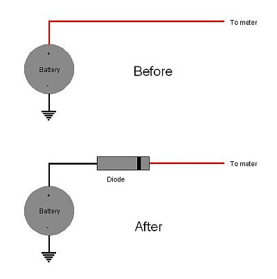
(picture credit to Jes)
It has to be a germanium diode, not silicon, in order to achieve the required 0.2v voltage reduction. This article has a helpful explanation
http://www.mypentax.com/Meter_Tech_diode.html
_________________
Peter - Moderator |
|
| Back to top |
|
|
fish4570
Joined: 06 Jan 2010
Posts: 4514
Location: At the confluence of the Locust Fork of the Warrior River and Black Creek, Alabama
Expire: 2012-03-21
|
| Posted: Sat Jan 23, 2010 10:02 pm Post subject: |
|
|
fish4570 wrote:
wow. even a schematic. thanks again. 
_________________
Paul
I chase Light
http://blackcreekjournal.blogspot.com/ |
|
| Back to top |
|
|
Kamerer

Joined: 24 Jun 2008
Posts: 389
Location: Russia Moscow
|
| Posted: Mon Jan 25, 2010 9:03 am Post subject: |
|
|
Kamerer wrote:
| peterqd wrote: |
The correct replacement battery, with the required insulating collar, is an Energizer 387S silver oxide cell. However the voltage output of this is 1.55v instead of the 1.35v of the old PX-400 mercury cell. This makes the needle over-react and causes pictures to be under-exposed by about 2 stops if you centre the needle.
The Spotmatic meter does indeed have a "bridge" circuit of sorts, but this doesn't automatically mean that higher voltage has no effect. The meter is designed so that the needle is centred when the exposure is correct, and this requires a small current, which IS affected by the voltage. In a proper "Wheatstone bridge" circuit used by more modern cameras, the current passing through the meter is zero when the exposure is correct, so the voltage is not critical.
One way round this is to set the ASA setting on the camera to 2 stops slower to compensate. Or you can use a Wein-Cell MRB-400 or hearing-aid zinc-air cell with correct 1.35v output, but they are expensive and short-lived, about 3 months. Once exposed to air, they continually produce power until they're exhausted, whether or not you use the camera.
Alternatively, you can modify the camera to compensate for the higher voltage. There are two ways - the easier way is to insert a diode into the battery wire in the base of the camera. This works fine while the battery is fresh and the temperature is normal. When the battery tires, or in extreme hot or cold, the voltage reduction effect is altered in a non-linear way, so the camera meter becomes unreliable. The other way is to insert two new resistors in the meter circuit to reduce the current in the meter to waht it should be. This means more work removing the top cover, but it's much more reliable. This thread explains how:
http://forum.mflenses.com/international-teamwork-fixing-spotmatics-t7047.html |
Effect of voltage on the testimony of the bridge galvanometer depends on the position of the galvanometer needle when deenergizing. If the needle is in the middle, then the voltage on the balance of influence will not. If the needle is at the limiter, the voltage on the balance of influence will be.
_________________
Sony NEX-3 + NEX C3
MC Helios-44M-4
VMC Vivitar 28-90/2.8-3.5 Ser1
Pentakta 2/30
My texts are translated by the electronic translator. Best regards, Sergey.
|
|
| Back to top |
|
|
peterqd
Joined: 28 Feb 2007
Posts: 7448
Location: near High Wycombe, UK
Expire: 2014-01-04
|
| Posted: Mon Jan 25, 2010 9:21 am Post subject: |
|
|
peterqd wrote:
| Kamerer wrote: |
| Effect of voltage on the testimony of the bridge galvanometer depends on the position of the galvanometer needle when deenergizing. If the needle is in the middle, then the voltage on the balance of influence will not. If the needle is at the limiter, the voltage on the balance of influence will be. |
That's exactly right Sergey. The needle on the Spotmatic is at the bottom limit pointing downwards when no current is flowing (de-energised). A current of 3µA is required to centre the needle. Thanks for confirming.
_________________
Peter - Moderator |
|
| Back to top |
|
|
erreoa
Joined: 24 Feb 2011
Posts: 1
|
| Posted: Mon Apr 04, 2011 6:09 pm Post subject: |
|
|
erreoa wrote:
| Quote: |
peterqd wrote:
That's exactly right Sergey. The needle on the Spotmatic is at the bottom limit pointing downwards when no current is flowing (de-energised). A current of 3µA is required to centre the needle. Thanks for confirming. |
First of all, I would like to thank all of you for your invaluable help on this subject. I am new to Spotties and trying to make it work this nice camera.
Second: Yes, I know this is a very old thread. So, forgive me (again, I am new here)
My Spotmatic is a IIa and what I can see in the viewfinder is a right bar with a + on top, a - on bottom, an opening in the center, with the needle "almost" centered when no battery is inserted in the camera. I am in the process of getting a 387S to test the camera for accuracy, but would appreciate your thoughts on the view I have just described: Do you believe that something is wrong with my meter?
Thanks in advance,
_________________
Raul |
|
| Back to top |
|
|
|
|
|
You cannot post new topics in this forum
You cannot reply to topics in this forum
You cannot edit your posts in this forum
You cannot delete your posts in this forum
You cannot vote in polls in this forum
|