| View previous topic :: View next topic |
| Author |
Message |
RokkorDoctor


Joined: 27 Nov 2021
Posts: 1268
Location: Kent, UK
|
 Posted: Fri Mar 18, 2022 11:32 pm Post subject: Minolta MC ROKKOR-PF 50mm f/2 near complete CLA Posted: Fri Mar 18, 2022 11:32 pm Post subject: Minolta MC ROKKOR-PF 50mm f/2 near complete CLA |
 |
|
RokkorDoctor wrote:
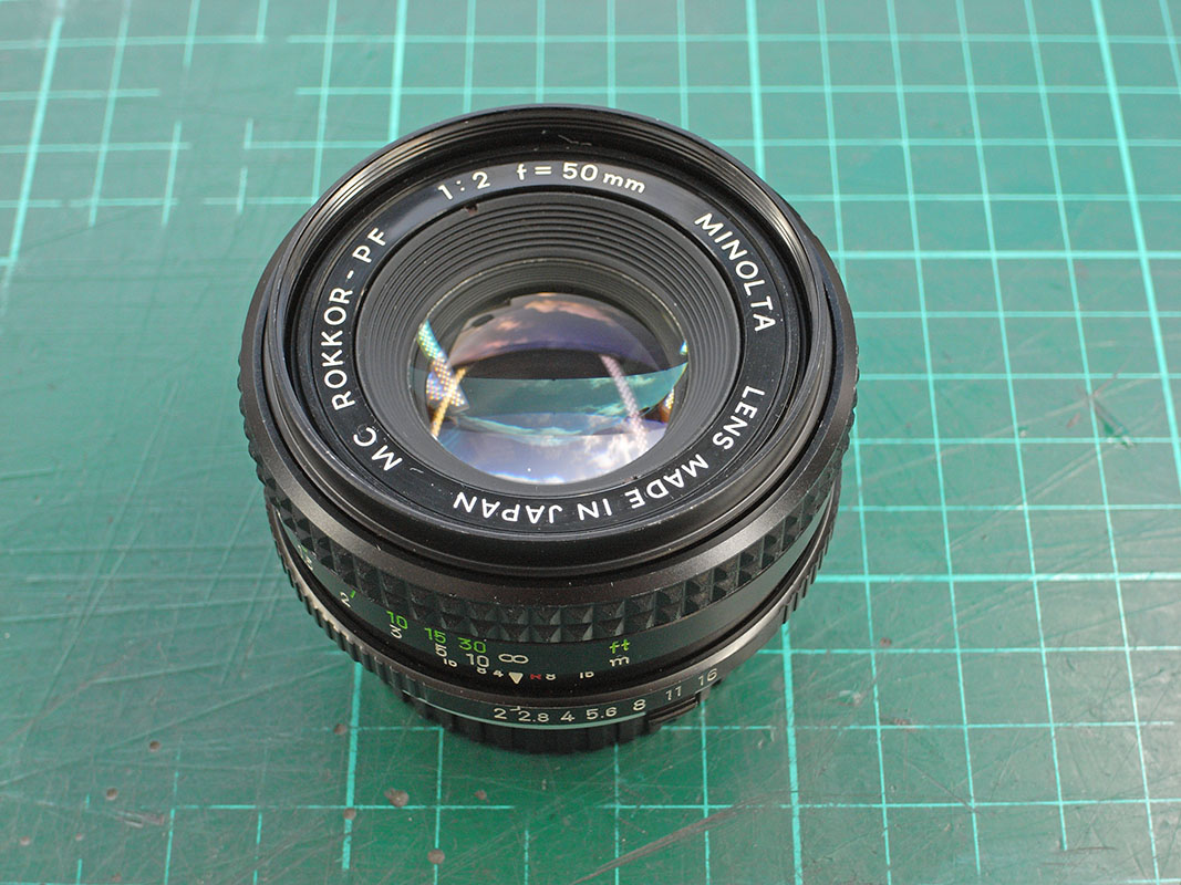
Folks, I recently got a MINOLTA MC ROKKOR-PF 50mm f/2 cheap because of a stuck aperture.
I thought I would fix this and document the CLA process I follow, which for this lens is only a partial one.
For me, it is an interesting opportunity to see where and how Minolta has done their cost-cutting, this being a budget lens that came as a set with the SRT100.
As this is a very simple lens, for the benefit of others it is a good one to demonstrate some of the general CLA (clean, lube, adjust) procedures I follow. Hopefully this is of use to anyone interested in the inner workings of such lenses, or who may not know where to start when getting into lens repair (It can be intimidating at first, not knowing where to start  ) )
NOTE: as these images are intended to clarify the inner workings & construction, I have lifted the shadows considerably on purpose, so contrast may seem low.
This is the patient for today:

I usually start by removing the rubber (vinyl actually) grip. This may reveal hidden screws, but also it makes cleaning the parts easier. No hidden screws here. On Minoltas these vinyl tubes usually just slide off, this one has some adhesive, but isn't really needed:

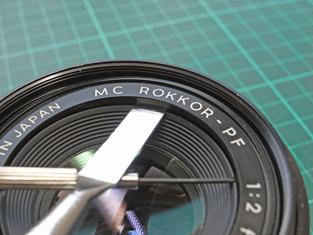
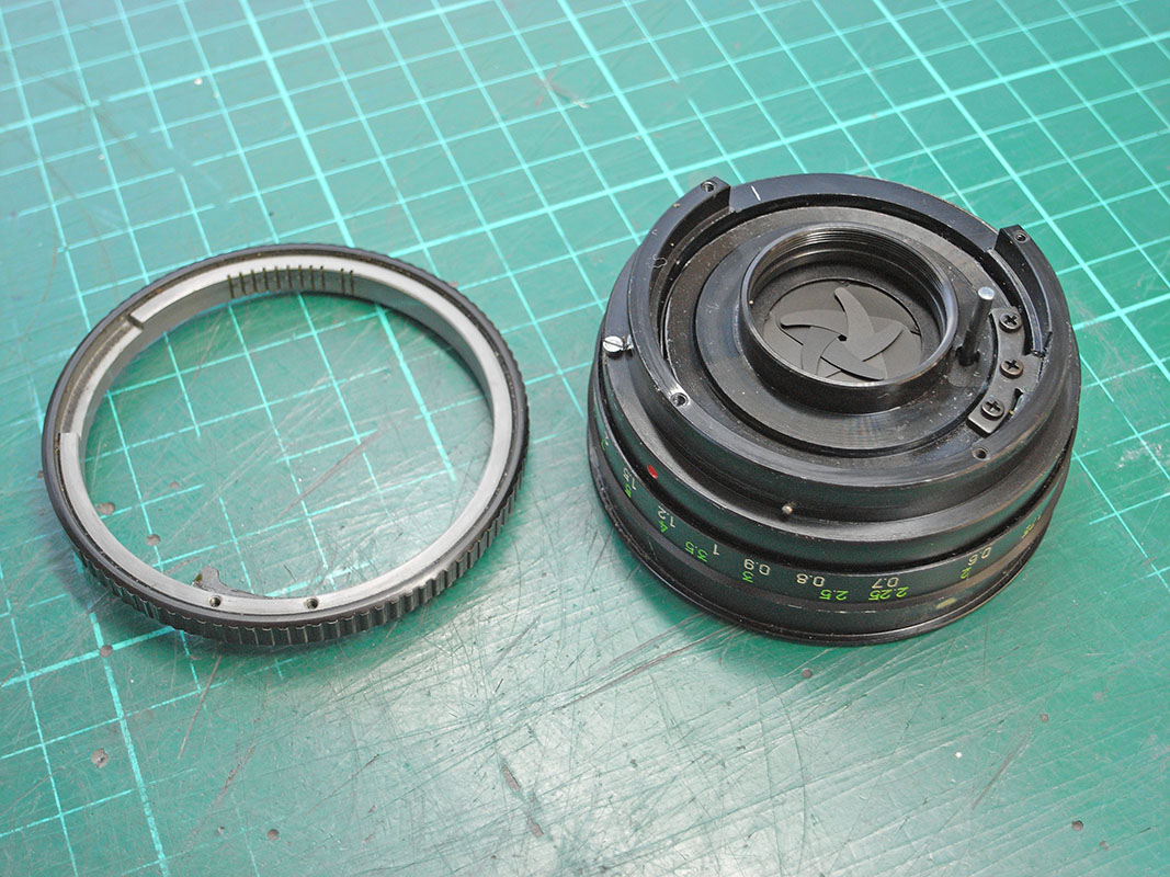
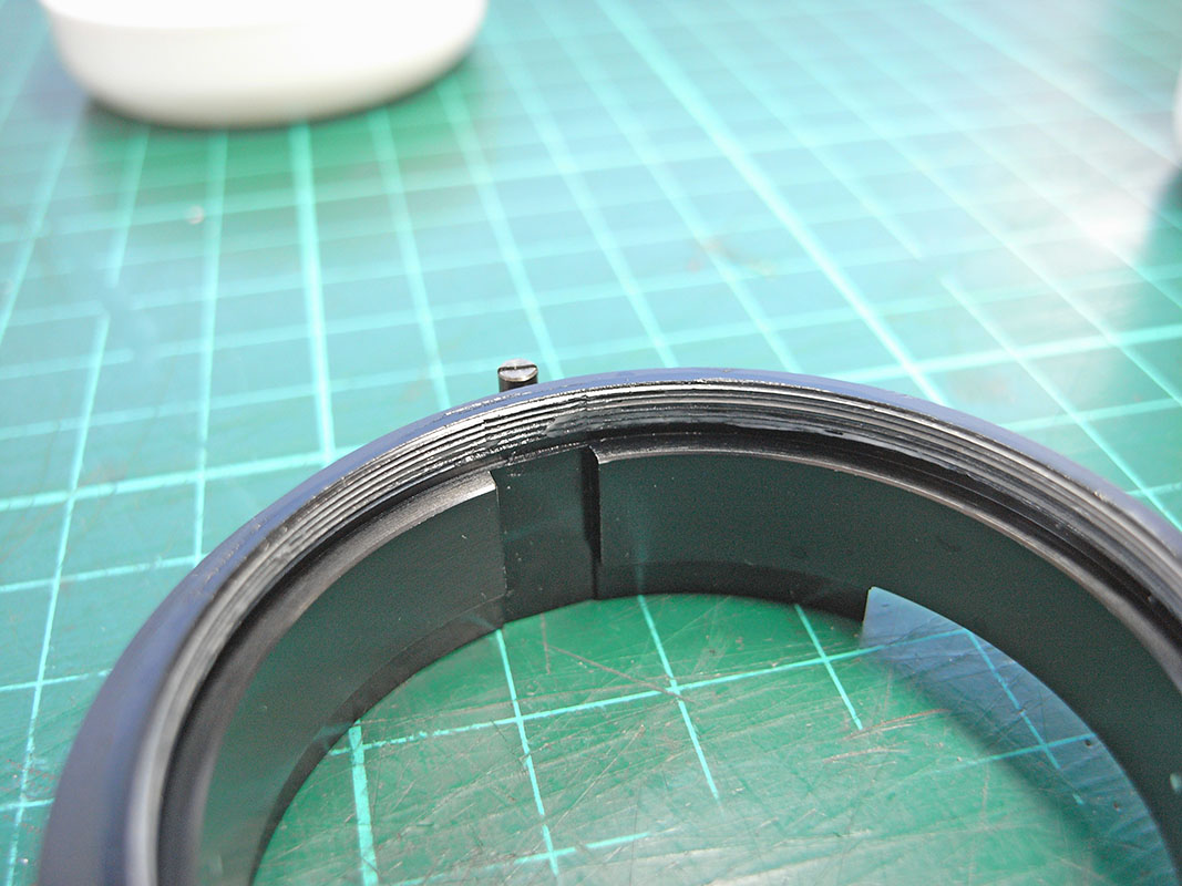
The next step (almost always) involves removal of the name ring. On most Minolta lenses these are screwed into the filter thread, or a secondary thread. This one however, is different: the filter thread ends above the name ring, and there is no visible evidence of a secondary thread:
(that is a rough looking thread end; maybe the first evidence of this being budget finishing)

My rubber removal tools have no effect, this name ring isn't screwed in and is not like the other Minolta name rings I have come across. A test with a thin screwdriver confirms this one is clipped/glued in:

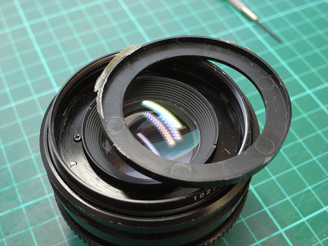
Sliding a second less scratch-prone pry-tool underneath, the name ring is released further:

Yes, this thing was clipped in with some additional adhesive for good measure. It clips in securely; I won't be replacing the adhesive later. Another sign of cost cutting: this name ring is cheaper to manufacture; it only requires a two-halve injection mould; adding a thread would increase production & tooling costs. The back of the name ring is evidence of a rough tooling finish of the mould, even if it is the non-visible side. Not like the usual Minolta injection-mould finish.

The filter holder needs to be removed in order to get access to the focus ring screws. This is pretty standard for Minolta lenses. Three screws need to be undone:

With the filter holder removed, we see the most common arrangement for collimation adjustment on Minolta Rokkor lenses: the focus ring is attached to the helicoid with three screws. Loosening these allows for the focus ring to be freely rotated and adjusted for proper infinity focus:

Switching focus to the back of the lens (which, ironically, is out of focus  ) it appears the black back cover does not need removing. Those screws turn out to be thread-locked anyway, so I will leave them. Odd, Minolta would not usually apply thread-lock on those screws, these is no stress on them and they do not hold anything in critical alignment. ) it appears the black back cover does not need removing. Those screws turn out to be thread-locked anyway, so I will leave them. Odd, Minolta would not usually apply thread-lock on those screws, these is no stress on them and they do not hold anything in critical alignment.
EDIT: I did later have to remove these screws: that black cover is an integral part with the three "lips" of the bayonet. One was slightly bent so I had to remove that cover to bend it straight. Didn't spot that the first time until I noticed the lens was a little loose on one of my adapters.

With a lens spanner wrench and some rubber tools I remove the front & rear cells. Here are the main parts we have removed so far:

For those not familiar with what spanner wrenches are, here are some. There is also a divider shown, which is only used for hard-to-reach places:

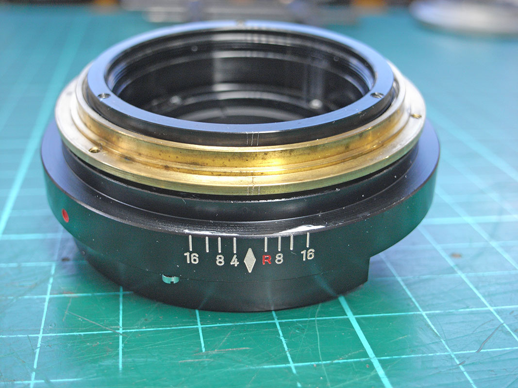
Four screws release the mount. Those familiar with Minolta Rokkor lenses will notice the next cost cutting measure: no separate cover that leaves the mount attached but gives access to the aperture adjust curve. Adjusting the aperture on this one is going to be a painful exercise. More on that later.

When removing the aperture ring on Minolta lenses, here is the most important part: keep your hand wrapped around it as there is a tiny (1mm) spring-loaded ball that will otherwise fly across the room never to be seen again. You can see that small ball at the bottom of the lens base:
The thing I noticed immediately that this aperture ring is not like most other minolta aperture rings. Usually they are of aluminium construction, subject to several complex turning and milling operations, and are normally black-anodised or matt-chromium plated. This one is a heavy metal casting, with the knurling moulded in and with a spray-painted black finish.
I also remove the small spring from the hole behind the aperture click-ball. I don't want to lose this when cleaning the lens base later on! This spring is tiny, maybe only 0.7mm diameter or so.

A common design feature on Minolta lenses: a screw on the lens base fits in a slot on the aperture ring, to limit the ring's rotation:

Next I mark the position of the fixing screws on the focus ring, so I can get it back to the correct position later on. On this lens focus is slightly short of infinity, so I will have to adjust it a bit afterwards anyway:

The focus ring is set to infinity, then the screws are carefully removed. The focus ring removed:

Another cost saving measure: the focus stops are screwed into the focus ring. On most other Minolta focus rings this would be an integral machined part of the ring. This here is cheaper, the ring will only need turning, and not an additional complex milling operation.
With the helicoid still set to infinity, I mark it up (I use three dashes, to differentiate my markings from any factory applied ones which are usually two dashes):

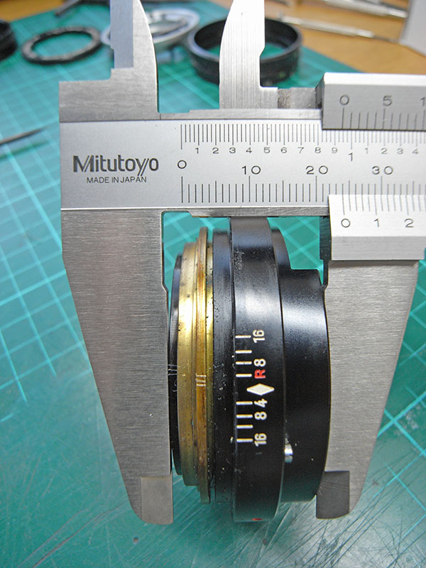
I take two measurements at the infinity setting for later reference: the gap between the lens base and brass helicoid ring, which is 1mm, and the overall length of the helicoid block, which is 23.92mm:

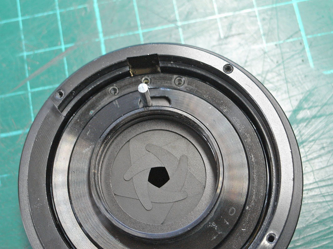
I also take note of the free aperture open diameter: 17mm, blades slightly over-retracted

And I take note of the free aperture closed diameter: 1.2mm:

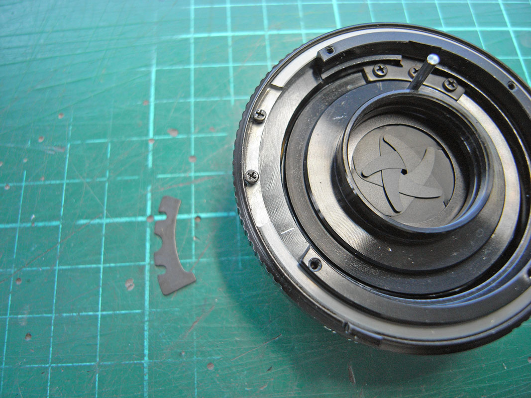
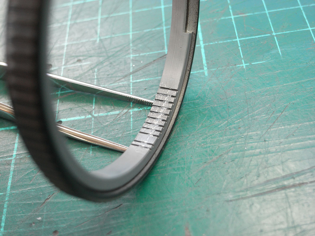
Now that we have taken note of all important reference measurements, it is time to remove the helicoid key. That thing in the image below is called the helicoid key, and it prevents the inner lens barrel from rotating as the focus grip is rotated. It slots into a slot, which is called the helicoid keyway.

With the helicoid key removed, the inner lens barrel can be rotated out of the brass helicoid part, but do this very slowly; at the point where the helicoid separates, an insertion mark needs to be made so that the helicoid can later be re-inserted on the correct one of its many possible starts!

This is the inner barrel removed. The course thread of the helicoid can clearly be seen , with all that lovely old grease with molybdenum disulfide dry-lube additive clearly visible:

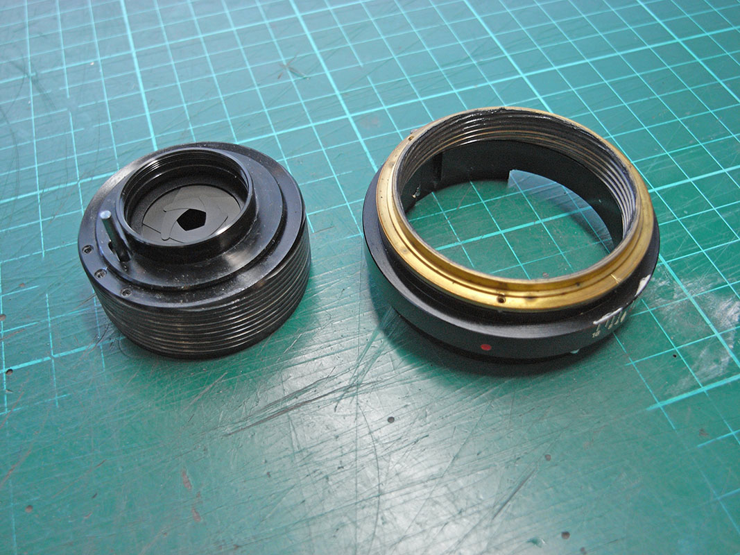
Both parts of the helicoid now removed. Visible are the course thread of the helicoid, as well as the fine thread of the helicoid. The brass part contains both the course and fine threads. The fine thread engages the lens base, the course thread engages the inner barrel. That is why camera manufacturers refer to this focus mechanism as a double helicoid focus mechanism.

I would now normally disassemble the aperture assembly, for cleaning of the stuck blades. Unfortunately, the retainer ring of this mechanism was fixed with an excessive amount of thread-lock, and one of the set-screws that fixes it was half-stripped in the factory. I could not remove it unfortunately, so the assembly can not be taken apart.

I would not normally advocate this, but for this lens the only way to clean the lubricant from the aperture mechanism was a bath in isopropyl alcohol, and lots of operations of the aperture blades. This will rinse the oil out, but it does take quite a while. I'm not a fan of an ultrasonic bath here; flammable liquids in an ultrasonic bath are not a great idea, and the vibration can cause excessive shining of the aperture blades. Good old elbow grease it is:

All other parts are cleaned. The grease of the helicoid parts is mostly removed with a wooden toothpick and further cleaned with so isopropyl alcohol and q-tips. The helicoid parts and most of the other exterior parts are then cleaned with liquid hand-soap and a toothbrush, rinsed under water and thoroughly dried. Now all is ready for re-assembly:

First the helicoid needs re-lubricating. These are the greases I will be using. Helimax-XP for the main helicoid threads (both course & fine, some people prefer to use a thinner one for the fine thread, but that is personal preference). For the helicoid key & keyway I will be using Japan Hobby Tools S3000, which is a very thick grease:

First I clean the helicoid threads with a fine clean brush, and re-engage both the course and fine threads, using all the alignment marks made earlier. I then set everything to the infinity marks and check that all measurements consistent with the ones I made earlier. All OK!
Then I unscrew the helicoid from its fine thread, but leave the course thread engaged. This will allow me to lubricate the course thread. The reason I fitted it dry first is that a lubricated multi-start helicoid thread is difficult to engage; you can’t feel it “click in”. I apply grease and slowly work it through the threads, removing any excess that comes out of the ends until the whole thread is covered in a thin film without any grease migrating to the ends when working the helicoid:

A small amount of grease is applied to the threads of the fine helicoid on both parts; what is shown below looks like a lot more grease than it actually is:

The fine helicoid is screwed together, and the 1mm gap originally measured is obtained with the alignment marks aligned. The course helicoid isn’t fully screwed in yet though, as we still need to lubricate the helicoid keyway:

Now we need to apply the S3000 grease to the side edges of the keyway where the helicoid key will make contact:

S3000 is a thick grease:

With the grease applied to the helicoid keyway, the inner barrel can be screwed in completely to the alignment mark:
And as expected, the helicoid key position ligns up with the keyway:
With the helicoid key refitted, the helicoid reassembly is complete:

The grease I am using for the aperture ring is Japan Hobby Tools S40:

I insert the small spring for the click-ball, then apply grease S40 on top of the spring, in the ball detents and on the inner surface of the aperture ring. On the inner surface only a very small amount needs to be applied.


This is the tricky bit: with the aperture ring almost fitted, the little click-ball needs to be placed on the grease on top of the spring. Then, using a flat-faced tool, the ball needs to be depressed into the hole against the small spring pressure, and the aperture ring needs to slide on top to trap the ball. Unfortunately I can’t take a picture whilst I am doing that!

Now the aperture control arc needs to be fitted. As you can see, the holes for the screws in that arc are not closed, and will allow for adjustment of the position of that arc:


We need to work out the required aperture diameters. This can be estimated from the open aperture, and f/# stop ratios.
The open aperture diameter is 17mm, but we need to check if at open aperture it is the aperture blades, or the inside lens diameter that form the effective stop at f/2. This is also 17mm, so that matches up nicely:

Therefore, the target aperture diameters are:
f/2 17.0mm
f/2.8 12.1mm
f/4 8.5mm
f/5.6 6.1mm
f/8 4.3mm
f/11 3.1mm
f/16 2.1mm
(please someone explain how you can insert tabs in the mflenses editor!)
Adjusting the aperture control arc to obtain the above values is a very sensitive adjustment. You may only be moving the arc plate by 50 microns at a time, and it will require a lot of iterations as adjusting the arc for the wide aperture side (f/2.8 ) also affects the smallest aperture (f/16) a bit. This takes time and patience!!!
And here the budget nature of this lens throws up an additional problem. As may be clear from the image below, the mount (with aperture control lever) will need to be fitted to test the aperture size. But the aperture control arc plate cannot be adjusted with the mount fitted. This means a lot of removing and refitting of the mount.
So here is a top tip: you really don’t want to be tightening and removing the mount screws 10 times or more!!! What I do is fit the mount loosely, but insert a couple of trimmed-back cocktail sticks into two opposing holes, to keep the mount in the correct alignment while doing the adjustment procedure. Much easier and much quicker than inserting and removing the mount screws every time the plate needs a bit more tweaking…

With the aperture adjusted and the mount reattached, focus tuns to the focusing grip (no pun intended )
Back off the helicoid a bit (from the infinity focus mark), mount the focus grip and align the screw marks made earlier with the holes. Finally insert and tighten the three screws that fix the focus grip to the helicoid:


The lens cells exterior glass surfaces are cleaned with acetone. The aperture chamber is cleaned of dust with a blower bulb, and the cells are reinserted. Hand-tight with the spanner-wrench is enough, no need to hire the services of a 200-pound gorilla here.
A final check that I am happy with the focus resistance, and that there is no excess grease being worked out of the helicoid threads:

The last thing to do is to fit the filter holder (serial number to the bottom!) and clip in the name ring, and the lens is complete!
So, I have to say that looking at the quality of materials and finish of this lens, this is definitely not quite up to Minolta’s usual standards. Definitely some cost-cutting on this budget lens. Excessively applied thread-lock, a mangled set-screw out of the factory (this lens looked like it had never been taken apart after leaving the factory), uneven engraving on the focus scale. A glued-in name ring. Less attention to detail on the injection-moulding tooling. It almost feels as if some critical components were made by Minolta (lenses, aperture assembly, anodised finish etc.), but that the manufacture of some other components and final assembly were contracted out. Either that, or these were the lenses they used to train their apprentices on!
_________________
Mark
SONY A7S, A7RII + dust-sealed modded Novoflex/Fotodiox/Rayqual MD-NEX adapters
Minolta SR-1, SRT-101/303, XD7/XD11, XGM, X700
Bronica SQAi
Ricoh GX100
Minolta majority of all Rokkor SR/AR/MC/MD models made
Sigma 14mm/3.5 for SR mount
Tamron SP 60B 300mm/2.8 (Adaptall)
Samyang T-S 24mm/3.5 (Nikon mount, DIY converted to SR mount)
Schneider-Kreuznach PC-Super-Angulon 28mm/2.8 (SR mount)
Bronica PS 35/40/50/65/80/110/135/150/180/200/250mm |
|
| Back to top |
|
 |
martinsmith99


Joined: 31 Aug 2008
Posts: 6943
Location: S Glos, UK
Expire: 2013-11-18
|
| Posted: Wed Mar 30, 2022 1:11 pm Post subject: |
|
|
martinsmith99 wrote:
Possibly made on a Friday afternoon.

_________________
Casual attendance these days |
|
| Back to top |
|
|
55

Joined: 13 May 2013
Posts: 709
Location: U.S.
Expire: 2022-06-15
|
| Posted: Sat Apr 02, 2022 3:55 pm Post subject: |
|
|
55 wrote:
 
Hats off to RokkorDoctor for the excellent and helpful documentation!
It takes a LOT of time, effort and knowledge to compile such a thorough, yet easy to follow tutorial.
| RokkorDoctor wrote: |
. . .
That thing in the image below is called the helicoid key, and it prevents the inner lens barrel from rotating as the focus grip is rotated. It slots into a slot, which is called the helicoid keyway. |
So that's what those are called!  |
|
| Back to top |
|
|
RokkorDoctor
Joined: 27 Nov 2021
Posts: 1268
Location: Kent, UK
|
| Posted: Sat Apr 02, 2022 4:31 pm Post subject: |
|
|
RokkorDoctor wrote:
| 55 wrote: |
| RokkorDoctor wrote: |
. . .
That thing in the image below is called the helicoid key, and it prevents the inner lens barrel from rotating as the focus grip is rotated. It slots into a slot, which is called the helicoid keyway. |
So that's what those are called! |
This lens has only one, offset to one side of the helicoid. It is not ideal, but you can get away with a single key for small (short) helicoids. Larger/longer helicoids usually have two helicoid keys, opposite each other (or at least they should have on the better lenses; two opposing keys prevent stiff focus & binding on longer helicoids).
_________________
Mark
SONY A7S, A7RII + dust-sealed modded Novoflex/Fotodiox/Rayqual MD-NEX adapters
Minolta SR-1, SRT-101/303, XD7/XD11, XGM, X700
Bronica SQAi
Ricoh GX100
Minolta majority of all Rokkor SR/AR/MC/MD models made
Sigma 14mm/3.5 for SR mount
Tamron SP 60B 300mm/2.8 (Adaptall)
Samyang T-S 24mm/3.5 (Nikon mount, DIY converted to SR mount)
Schneider-Kreuznach PC-Super-Angulon 28mm/2.8 (SR mount)
Bronica PS 35/40/50/65/80/110/135/150/180/200/250mm |
|
| Back to top |
|
|
55
Joined: 13 May 2013
Posts: 709
Location: U.S.
Expire: 2022-06-15
|
| Posted: Thu Apr 07, 2022 5:01 am Post subject: |
|
|
55 wrote:
Thanks, Mark. I'll be aware of that from now on. I know I've cleaned at least one lens which has a single key.
Maybe I can find it if I check my notes. |
|
| Back to top |
|
|
Doc Sharptail

Joined: 23 Nov 2020
Posts: 993
Location: Winnipeg Canada
|
| Posted: Tue Apr 12, 2022 3:57 am Post subject: |
|
|
Doc Sharptail wrote:
Nice to see a manual mike being used.
That's how I found out how far sighted I am, and explains a lot of the oof junk images I get at times without my glasses.
Spent a bit of time scrolling up and down to figure out what your work surface is, and can't quite come up with a sufficient answer.
I usually work over a good masonite table-top. For rolling parts, an old mouse pad does wonders, as long as the bottom isn't too crumbly.
-D.S.
_________________
D-810, F2, FTN.
35mm f2 O.C. nikkor
50 f2 H nikkor, 50 f 1.4 AI-s, 135 f3.5 Q,
50 f2 K nikkor 2x, 28-85mm f3.5-4.5 A/I-s, 35-105 3.5-4.5 A/I-s, 200mm f4 Micro A/I, partial list.
"Ain't no half-way" -S.R.V.
"Oh Yeah... Alright" -Paul Simon |
|
| Back to top |
|
|
RokkorDoctor
Joined: 27 Nov 2021
Posts: 1268
Location: Kent, UK
|
| Posted: Tue Apr 12, 2022 8:59 am Post subject: |
|
|
RokkorDoctor wrote:
| Doc Sharptail wrote: |
Nice to see a manual mike being used.
That's how I found out how far sighted I am, and explains a lot of the oof junk images I get at times without my glasses.
Spent a bit of time scrolling up and down to figure out what your work surface is, and can't quite come up with a sufficient answer.
I usually work over a good masonite table-top. For rolling parts, an old mouse pad does wonders, as long as the bottom isn't too crumbly.
-D.S. |
When you say "mike" I assume you mean those Mitutoyo vernier calipers, those are a a hand-me-down from my dad from the days when he was working in the Dutch national aerospace research facilities. If looked after and used appropriately, those manual Mitutoyo measurement tools last a generation or longer
I later got myself some additional Mitutoyo dial & verier depth gauges and an outside micrometer as well. All necessary for working to 35mm format depth-of-focus tolerances.
That work surface is a standard green cutting-mat that has seen much better days, on top of a wooden table in my garage.
When I say garage, it is a very recent (re-)build. The old garage was subsiding, and we had to have it demolished and a completely new one built. Whilst technically it still is a garage in order to comply with local planning rules, there are no cars in it, it is well-insulated, sealed, temperature and humidity-controlled with large windows giving good lighting; more of a man-cave/workshop/studio really. No more condensation, mould & rusty tools )
_________________
Mark
SONY A7S, A7RII + dust-sealed modded Novoflex/Fotodiox/Rayqual MD-NEX adapters
Minolta SR-1, SRT-101/303, XD7/XD11, XGM, X700
Bronica SQAi
Ricoh GX100
Minolta majority of all Rokkor SR/AR/MC/MD models made
Sigma 14mm/3.5 for SR mount
Tamron SP 60B 300mm/2.8 (Adaptall)
Samyang T-S 24mm/3.5 (Nikon mount, DIY converted to SR mount)
Schneider-Kreuznach PC-Super-Angulon 28mm/2.8 (SR mount)
Bronica PS 35/40/50/65/80/110/135/150/180/200/250mm |
|
| Back to top |
|
|
Doc Sharptail
Joined: 23 Nov 2020
Posts: 993
Location: Winnipeg Canada
|
| Posted: Tue Apr 12, 2022 1:24 pm Post subject: |
|
|
Doc Sharptail wrote:
I used the exact same set as in your photo's at work- mostly to get proper diameters for blown fan shaft bearings.
They were more precise than the plastic digital dial caliper- which is sort of an important lesson to learn with the price of today's bearings.
I have two of the outside caliper sets. Both are a little small for camera work at 1" and 1-1/2". One is Mitutoyo, and the other is a generic of some sort. Both still see sporadic duty around here for my "other" hobbies.
-D.S.
_________________
D-810, F2, FTN.
35mm f2 O.C. nikkor
50 f2 H nikkor, 50 f 1.4 AI-s, 135 f3.5 Q,
50 f2 K nikkor 2x, 28-85mm f3.5-4.5 A/I-s, 35-105 3.5-4.5 A/I-s, 200mm f4 Micro A/I, partial list.
"Ain't no half-way" -S.R.V.
"Oh Yeah... Alright" -Paul Simon
Last edited by Doc Sharptail on Tue Apr 12, 2022 1:54 pm; edited 1 time in total |
|
| Back to top |
|
|
Raxar

Joined: 25 Mar 2014
Posts: 222
|
| Posted: Tue Apr 12, 2022 1:30 pm Post subject: |
|
|
Raxar wrote:
|
|
| Back to top |
|
|
Sakyaputta

Joined: 01 Feb 2022
Posts: 52
Location: Beijing, China
|
| Posted: Fri May 06, 2022 12:25 pm Post subject: |
|
|
Sakyaputta wrote:
Excellent step-by-step documentation/tutorial, Rokkor Doctor! 👍 I've learned a lot from this post! All the best to you! 🙏 |
|
| Back to top |
|
|
|
|
|
You cannot post new topics in this forum
You cannot reply to topics in this forum
You cannot edit your posts in this forum
You cannot delete your posts in this forum
You cannot vote in polls in this forum
|