| View previous topic :: View next topic |
| Author |
Message |
leonknook
Joined: 10 Sep 2019
Posts: 9
Location: Netherlands
|
 Posted: Sat Sep 14, 2019 7:15 pm Post subject: Where to put aperture for a 400mm lens Posted: Sat Sep 14, 2019 7:15 pm Post subject: Where to put aperture for a 400mm lens |
 |
|
leonknook wrote:
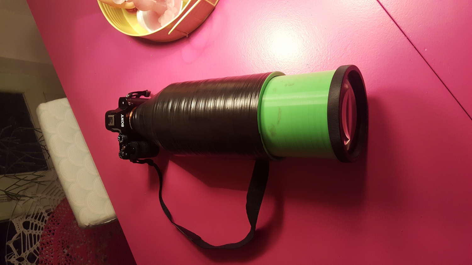
I'm building a huge Leica lens from a episcope diameter 12cm. I can 3D print what I want but I don't know where to put the 3D printed aperture. I see online standalone aperture rings and they will be mounted close to the sensor. But when you look at a normal lens the aperture is somewhere in the middle. Is there a rule for this?


look here for 3d printed aperture
https://youtu.be/wQnrqH53Npo
This is what I got so far. I found the focus distance for infinity and roughly I can make already some photos. The inside of the lens is green which is of course is wrong it should be Matt black. I have to print everything again with aperture using black plastic for the final version.
kind regards.
Leon |
|
| Back to top |
|
 |
leonknook
Joined: 10 Sep 2019
Posts: 9
Location: Netherlands
|
| Posted: Sat Sep 14, 2019 7:47 pm Post subject: |
|
|
leonknook wrote:
I don't see the uploaded pictures that I uploaded from my inline gallery?
After posting this message they where suddenly visible, weird! |
|
| Back to top |
|
|
aidaho


Joined: 29 Apr 2018
Posts: 456
Location: Ukraine
|
| Posted: Sat Sep 14, 2019 8:49 pm Post subject: |
|
|
aidaho wrote:
I've recently tried to answer the same question: http://forum.mflenses.com/canon-fd-4-5-400mm-vs-novoflex-5-6-400mm-t-t80838.html#1528109
TL;DR: if lens wasn't deigned for aperture, there isn't a "correct" place to put it, just the ones of varying degrees of inefficiency.
Without a raytrace of the lens optical scheme, for a lens this long, I would recommend a simple front filter thread aperture.
_________________
https://www.flickr.com/photos/curry-hexagon/ |
|
| Back to top |
|
|
leonknook
Joined: 10 Sep 2019
Posts: 9
Location: Netherlands
|
| Posted: Sun Sep 15, 2019 2:14 pm Post subject: |
|
|
leonknook wrote:
Thank you for your explanation. There are two options that I can try to see what the results are. An aperture directly at the backside of the lens in the form of a thin black plate with a hole in it (That is an aperture isn't it 


The second option is to print and mount the variable aperture close to the sensor.


all 3 glued together |
|
| Back to top |
|
|
Teemō

Joined: 07 Apr 2016
Posts: 586
Location: Australia
|
| Posted: Sun Sep 15, 2019 4:01 pm Post subject: |
|
|
Teemō wrote:
If you want to take a punt on at least the front element or group, then you'll want read Chapter 12 of Lens Design Fundamentals by R. Kingslake and ray trace by hand or input your lens values if known into a free Raytracer - at best it's an approximation and something new to learn.
My understanding is that these projector lenses were never designed for an aperture stop, and I didn't see any in such patents, and they didn't require high resolution. Of course, putting an aperture in could actually make some aberrations worse if they already equalise each other, but the easiest way to determine a good placement is empirically, so I'd suggest making a new prototype where you can slide the aperture along the length of the lens and directly view the image qualities. If the lens up front is the only optic in the system then the best aperture placement is likely to be between elements but if that's not possible then you are best to find the placement as above. The projection lens is probably a Petzval type, or a triplet. |
|
| Back to top |
|
|
leonknook
Joined: 10 Sep 2019
Posts: 9
Location: Netherlands
|
| Posted: Sun Sep 15, 2019 6:05 pm Post subject: |
|
|
leonknook wrote:
| Teemō wrote: |
| If you want to take a punt on at least the front element or group, then you'll want read Chapter 12 of Lens Design Fundamentals by R. Kingslake and ray trace by hand or input your lens values if known into a free Raytracer - at best it's an approximation and something new to learn. |
Thank you for pointing me to a more scientific way to calculate ray tracing and what not. All that is way above my intelligence. I'm a guy that builds stuff and learn by trail and error. No lens values available
| Teemō wrote: |
| My understanding is that these projector lenses were never designed for an aperture stop, and I didn't see any in such patents, and they didn't require high resolution. Of course, putting an aperture in could actually make some aberrations worse if they already equalize each other, but the easiest way to determine a good placement is empirically, so I'd suggest making a new prototype where you can slide the aperture along the length of the lens and directly view the image qualities. |
That's a very clever idea to design an aperture slider. Unfortunately I am already to far in this design and printed the most parts of it. But I keep this in mind!
| Teemō wrote: |
| If the lens up front is the only optic in the system then the best aperture placement is likely to be between elements but if that's not possible then you are best to find the placement as above. The projection lens is probably a Petzval type, or a triplet. |
What you see in the picture is the only optic and it is not possible to make something in between the lens elements.
 |
|
| Back to top |
|
|
GoldMark

Joined: 21 Aug 2012
Posts: 185
Location: Germany
|
| Posted: Sun Sep 15, 2019 8:08 pm Post subject: |
|
|
GoldMark wrote:
Wow. You created your own lens. my respect. Will we see the results with this lens?
_________________
Best regards
Bernhard
https://deramateurphotograph.de/ |
|
| Back to top |
|
|
leonknook
Joined: 10 Sep 2019
Posts: 9
Location: Netherlands
|
| Posted: Sun Sep 15, 2019 8:21 pm Post subject: |
|
|
leonknook wrote:
| GoldMark wrote: |
| Wow. You created your own lens. my respect. Will we see the results with this lens? |
I'm in the middle of the building but sure I will post the results.
The real credits for this goes to Ernst Leitz, I'm only printing some plastics around the elements
 |
|
| Back to top |
|
|
Teemō
Joined: 07 Apr 2016
Posts: 586
Location: Australia
|
| Posted: Mon Sep 16, 2019 9:40 am Post subject: |
|
|
Teemō wrote:
Interesting way to make the aperture blades! Is there a particular reason you made them geared?
I have modelled a lens housing in Inventor but wasn't sure how best to do the ends of the helical thread. Had to extrude a new part at the end, apply the chamfer so that it would go down onto the first thread, but I'm still not sure it's accurate to manufacture, particularly as there was some undercut. Obviously, the undercuts are formed as the lathe withdraws from the material but that's not what happens when it's made on a multi-axis CNC or 3d-printed. My threads are much smaller than yours, though.
What material have you used and what has been the overall cost to print, or how much material was used if you this is your own printer? |
|
| Back to top |
|
|
leonknook
Joined: 10 Sep 2019
Posts: 9
Location: Netherlands
|
| Posted: Mon Sep 16, 2019 2:28 pm Post subject: |
|
|
leonknook wrote:
| Teemō wrote: |
| Interesting way to make the aperture blades! Is there a particular reason you made them geared? |
I did not make this aperture by myself it is a download from https://www.thingiverse.com/thing:2847173
| Teemō wrote: |
| What material have you used and what has been the overall cost to print, or how much material was used if you this is your own printer? |
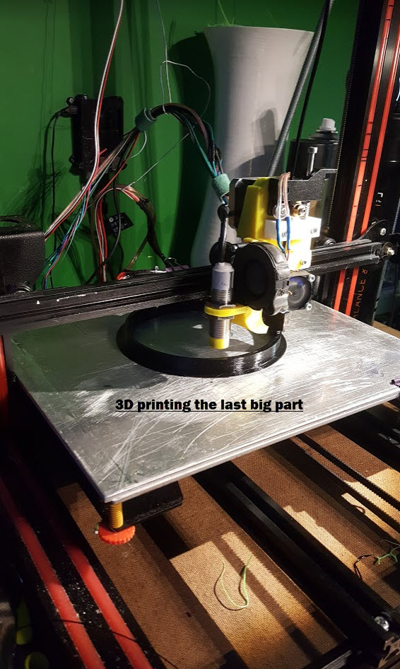
For the big parts I used standard black PLA plastic. For the aperture and camera mount part I use ASA (better then ABS) because this must be stronger than PLA.
The big parts take roughly 1.5 kilo PLA x $15 = $22.50 The few pieces of ASA will cost something around $5,- I was lucky to get the episcope with the big lens in it for $25.

I have several 3D printers at home. |
|
| Back to top |
|
|
Teemō
Joined: 07 Apr 2016
Posts: 586
Location: Australia
|
| Posted: Tue Sep 17, 2019 7:33 am Post subject: |
|
|
Teemō wrote:
Nice, cheaper than I expected. It would cost a fortune to print through a third-party service because of the size. I hope the aperture works out okay at the larger size, considering how much friction is demonstrated in the Thingiverse video. Looking forward to seeing the images from it.  |
|
| Back to top |
|
|
leonknook
Joined: 10 Sep 2019
Posts: 9
Location: Netherlands
|
| Posted: Sun Sep 22, 2019 6:59 pm Post subject: |
|
|
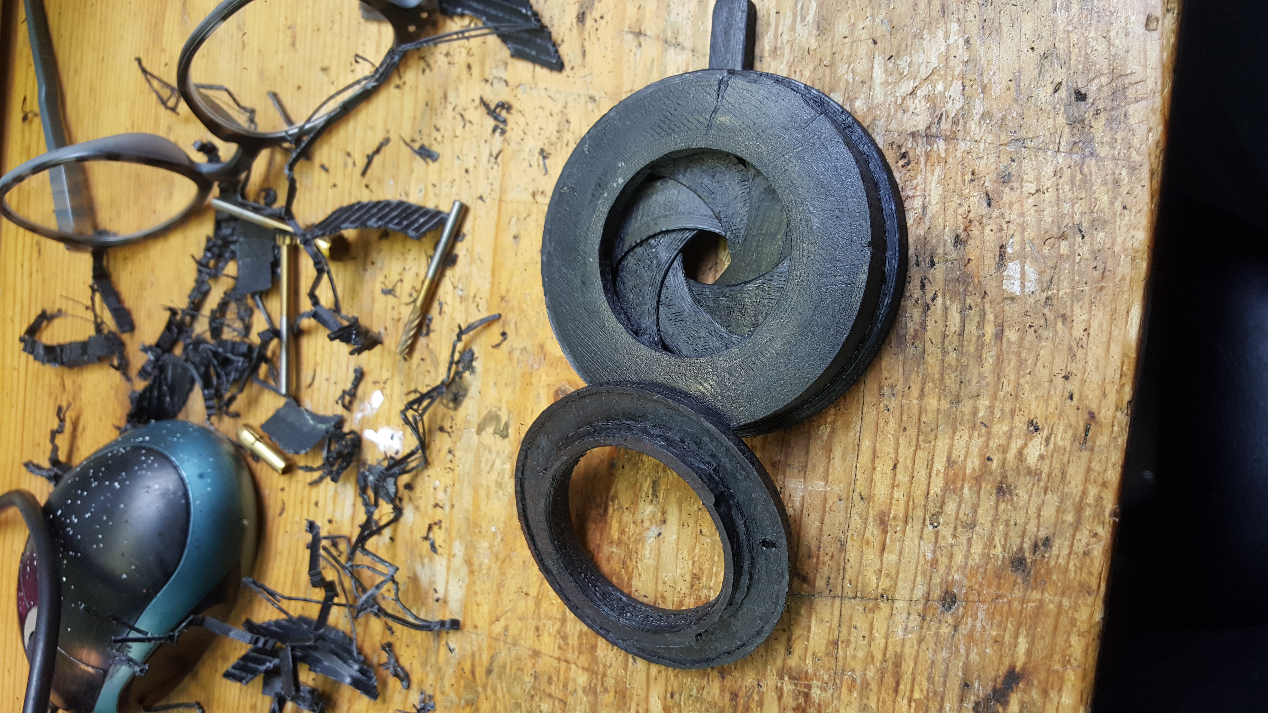
leonknook wrote:
Had to change the aperture to another model. It was almost impossible to assemble the first one.
This one was quite easy to put together. A lot of time spend on the post processing of the parts.

These are all very ugly 3D prints.

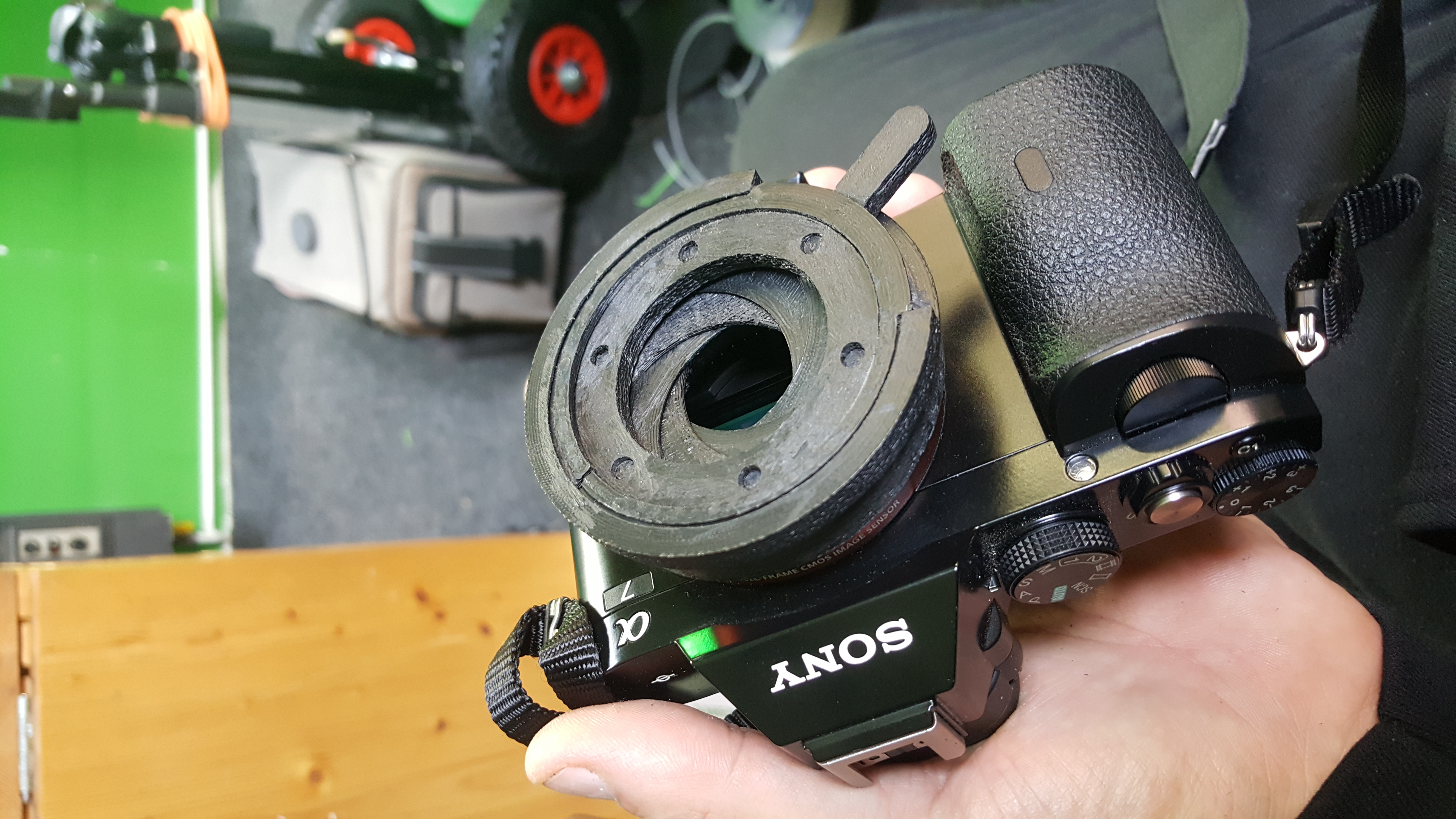
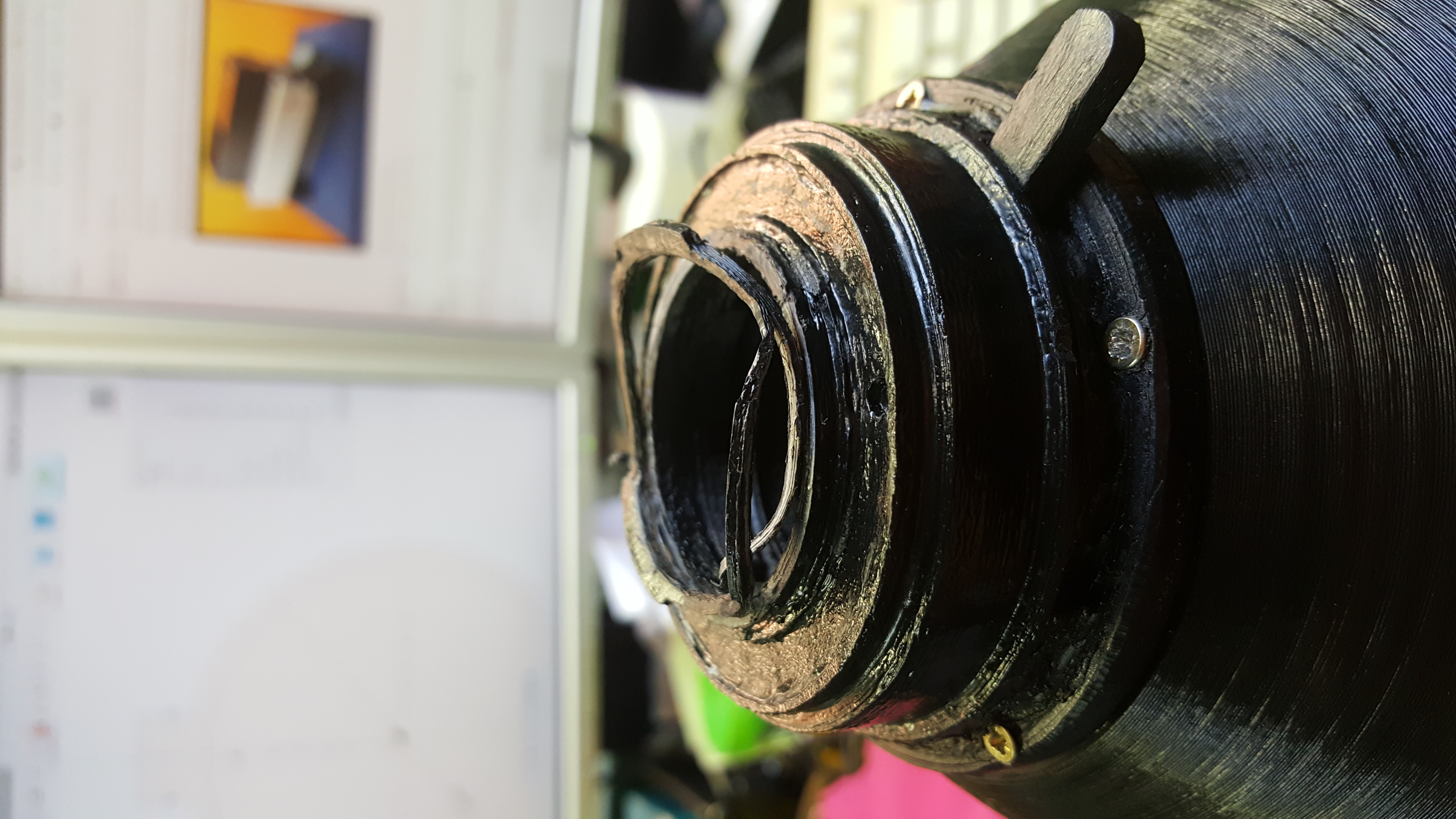
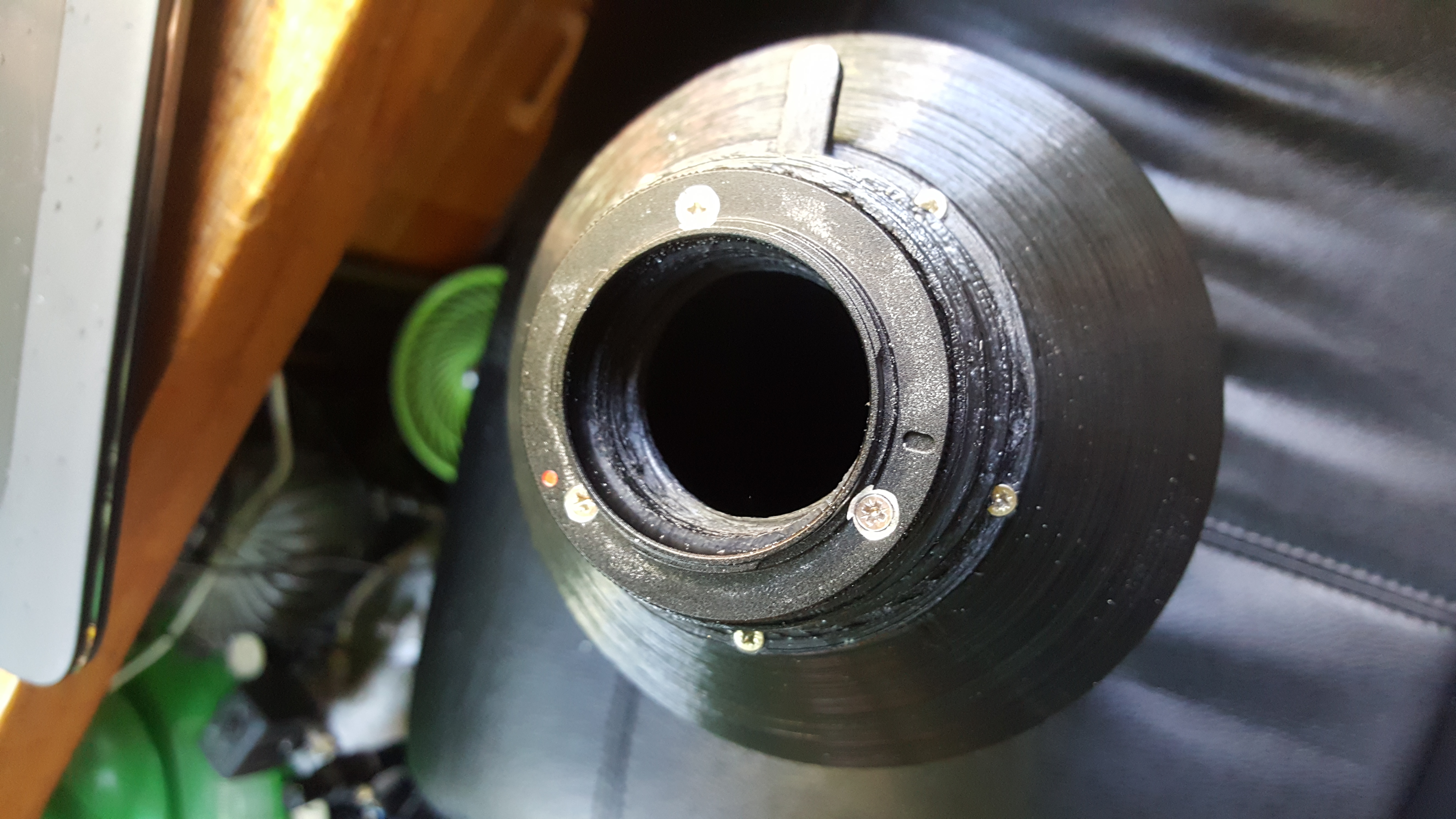
After gluing, melting and screwing several parts together I finally got an aperture with camera mount on my camera.


After assembling the aperture to the lens body I took some pictures, but O boy this lens is so heavy, 2.5 kilo !
It was impossible to shoot by hand so the pictures were bad and because of the stress of handling the weight the lens broke of the camera.
It is tricky to 3D print with plastics I knew that, so no damage on lens or camera.

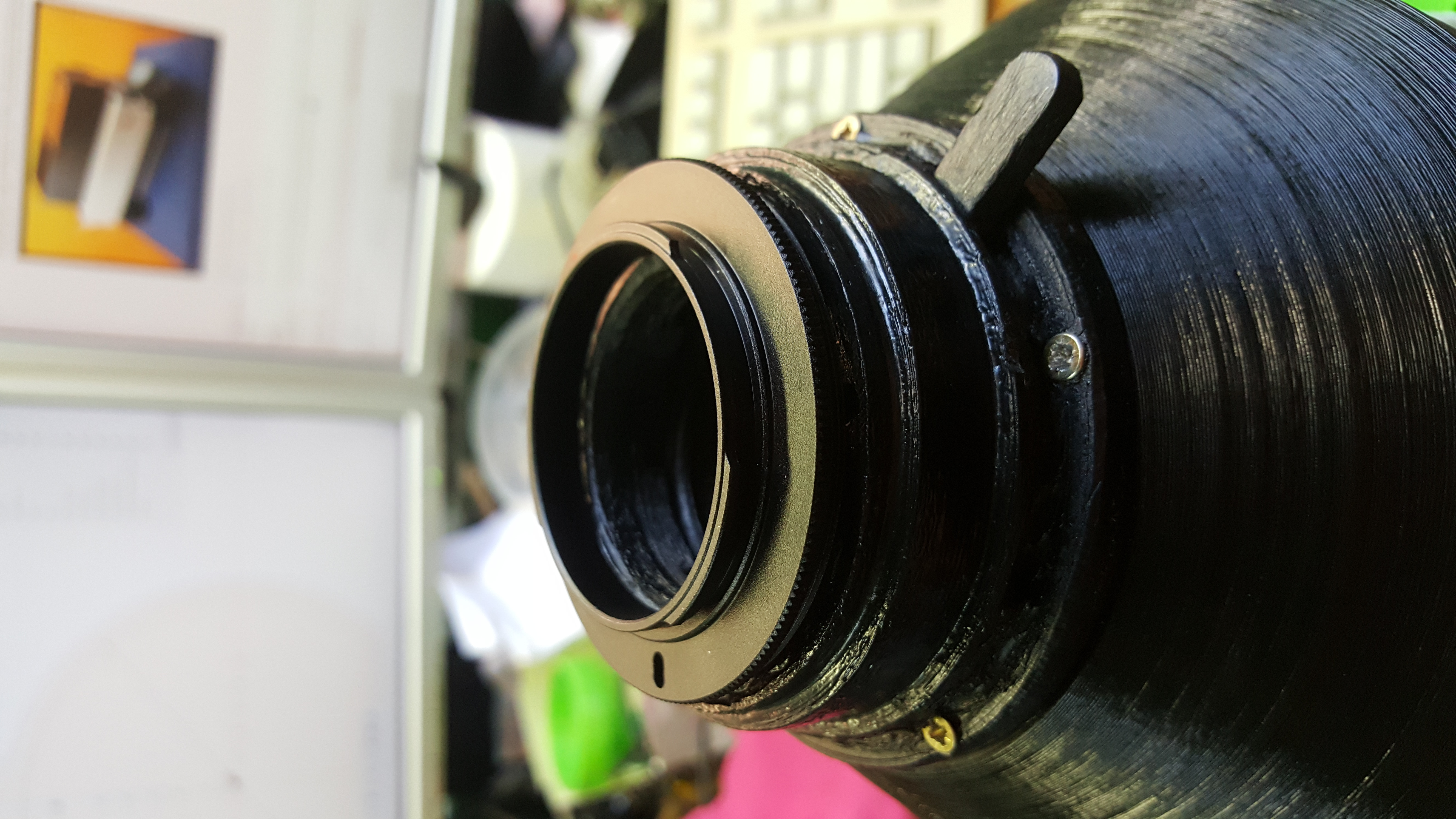
I had a lens reversal ring lying around which I could use to make a metal camera connection.


I drilled 3 holes in the ring and screwed it to the aperture.
Again outside trying to make some pictures.

The results are (at this point) disappointing. With the aperture wide open there is some little black shading in the corners. When pulling the slider to a smaller aperture hole, this got even worse. The depth of sharpness is very small and with max aperture the depth of field did not improve that much. I took maybe 50 photos and could not find pin sharp areas in any of them. There is much lens flair when pointing somewhat to the sun, maybe a good lens hood will help. Next step is to make a really sturdy mount on the lens to put the monster on a tripod. 
I will come back!
 |
|
| Back to top |
|
|
aidaho
Joined: 29 Apr 2018
Posts: 456
Location: Ukraine
|
| Posted: Sun Sep 22, 2019 9:12 pm Post subject: |
|
|
aidaho wrote:
| leonknook wrote: |
| The results are (at this point) disappointing. With the aperture wide open there is some little black shading in the corners. When pulling the slider to a smaller aperture hole, this got even worse. The depth of sharpness is very small and with max aperture the depth of field did not improve that much. |
Cool 3D-printed aperture.
But I did mention this can go pretty much backwards of what one would expect from aperture.
I still urge you to make a hole in something and stick it to the front.
It's not as cool as what you did, but for 400mm of unknown optical design it seems to me as more sound choice than a rear aperture.
_________________
https://www.flickr.com/photos/curry-hexagon/ |
|
| Back to top |
|
|
visualopsins


Joined: 05 Mar 2009
Posts: 10531
Location: California
Expire: 2025-04-11
|
| Posted: Mon Sep 23, 2019 1:40 am Post subject: |
|
|
visualopsins wrote:
That's what I was thinking too...aperture should go just behind lens. Near camera acts as baffle merely blocking the image circle not cutting off Ray's from outer portion of lens surface . Front of lens should work too. Useful experiment is using a solid circle instead of a hole, something like the blocked part front of mirror lens -- see how the Ray's from the outer portion of the lens surface comapare to this from the center portion through the hole. the
_________________
☮☮☮☮☮☮☮☮☮☮☮☮☮☮☮☮☮☮☮☮☮☮☮☮☮☮☮☮☮☮☮☮ like attracts like! ☮☮☮☮☮☮☮☮☮☮☮☮☮☮☮☮☮☮☮☮☮☮☮☮☮☮☮☮☮☮☮☮
Cameras: Sony ILCE-7RM2, Spotmatics II, F, and ESII, Nikon P4
Lenses:
M42 Asahi Optical Co., Takumar 1:4 f=35mm, 1:2 f=58mm (Sonnar), 1:2.4 f=58mm (Heliar), 1:2.2 f=55mm (Gaussian), 1:2.8 f=105mm (Model I), 1:2.8/105 (Model II), 1:5.6/200, Tele-Takumar 1:5.6/200, 1:6.3/300, Macro-Takumar 1:4/50, Auto-Takumar 1:2.3 f=35, 1:1.8 f=55mm, 1:2.2 f=55mm, Super-TAKUMAR 1:3.5/28 (fat), 1:2/35 (Fat), 1:1.4/50 (8-element), Super-Multi-Coated Fisheye-TAKUMAR 1:4/17, Super-Multi-Coated TAKUMAR 1:4.5/20, 1:3.5/24, 1:3.5/28, 1:2/35, 1:3.5/35, 1:1.8/85, 1:1.9/85 1:2.8/105, 1:3.5/135, 1:2.5/135 (II), 1:4/150, 1:4/200, 1:4/300, 1:4.5/500, Super-Multi-Coated Macro-TAKUMAR 1:4/50, 1:4/100, Super-Multi-Coated Bellows-TAKUMAR 1:4/100, SMC TAKUMAR 1:1.4/50, 1:1.8/55
M42 Carl Zeiss Jena Flektogon 2.4/35
Contax Carl Zeiss Vario-Sonnar T* 28-70mm F3.5-4.5
Pentax K-mount SMC PENTAX ZOOM 1:3.5 35~105mm, SMC PENTAX ZOOM 1:4 45~125mm
Nikon Micro-NIKKOR-P-C Auto 1:3.5 f=55mm, NIKKOR-P Auto 105mm f/2.5 Pre-AI (Sonnar), Micro-NIKKOR 105mm 1:4 AI, NIKKOR AI-S 35-135mm f/3,5-4,5
Tamron SP 17mm f/3.5 (51B), Tamron SP 17mm f/3.5 (51BB), SP 500mm f/8 (55BB), SP 70-210mm f/3.5 (19AH)
Vivitar 100mm 1:2.8 MC 1:1 Macro Telephoto (Kiron)
|
|
| Back to top |
|
|
leonknook
Joined: 10 Sep 2019
Posts: 9
Location: Netherlands
|
| Posted: Mon Sep 23, 2019 7:44 am Post subject: |
|
|
leonknook wrote:
| aidaho wrote: |
But I did mention this can go pretty much backwards of what one would expect from aperture.
I still urge you to make a hole in something and stick it to the front.
It's not as cool as what you did, but for 400mm of unknown optical design it seems to me as more sound choice than a rear aperture. |
| visualopsins wrote: |
| That's what I was thinking too...aperture should go just behind lens. Near camera acts as baffle merely blocking the image circle not cutting off Ray's from outer portion of lens surface . Front of lens should work too. Useful experiment is using a solid circle instead of a hole, something like the blocked part front of mirror lens -- see how the Ray's from the outer portion of the lens surface compare to this from the center portion through the hole. |
That is exactly what I intent to do. It is really easy to 3D print a black round disk with a hole in it. At first I want to make one right behind the lens. I did that earlier with a 90mm lens which causes black vignetting too, but we will see. At the front of the lens will work but the amount of light coming in will be reduced a lot. You will have to crank up your ASA which causes noise etc.... I will test all possibilities. Thank you for bearing with me and pointing me to options. |
|
| Back to top |
|
|
aidaho
Joined: 29 Apr 2018
Posts: 456
Location: Ukraine
|
| Posted: Mon Sep 23, 2019 11:23 am Post subject: |
|
|
aidaho wrote:
| leonknook wrote: |
| At the front of the lens will work but the amount of light coming in will be reduced a lot. You will have to crank up your ASA which causes noise etc.... |
It is indeed the whole point of the aperture: to significantly cut light from the outer portions of the glass.
Buy a sheet of thick black paper from the nearest office supplies store and cut several round openings.
Somewhere in the 80-40mm range. Test them to determine if any of them work for you and then consider 3D-printing one.
Don't sweat the precise shape or alignment during tests, it's not that important.
Black postcard-like paper will actually work better than the printed thick plastic aperture.
This is because it would be thinner and less reflective at the edges.
_________________
https://www.flickr.com/photos/curry-hexagon/ |
|
| Back to top |
|
|
leonknook
Joined: 10 Sep 2019
Posts: 9
Location: Netherlands
|
| Posted: Mon Sep 23, 2019 7:02 pm Post subject: |
|
|
leonknook wrote:
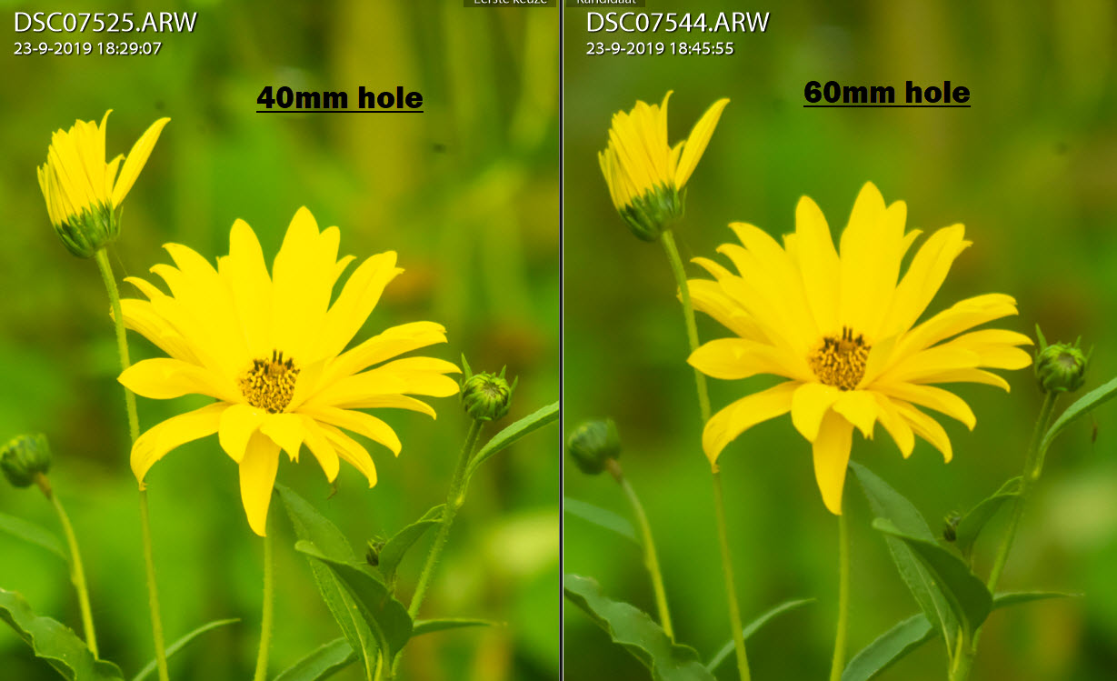
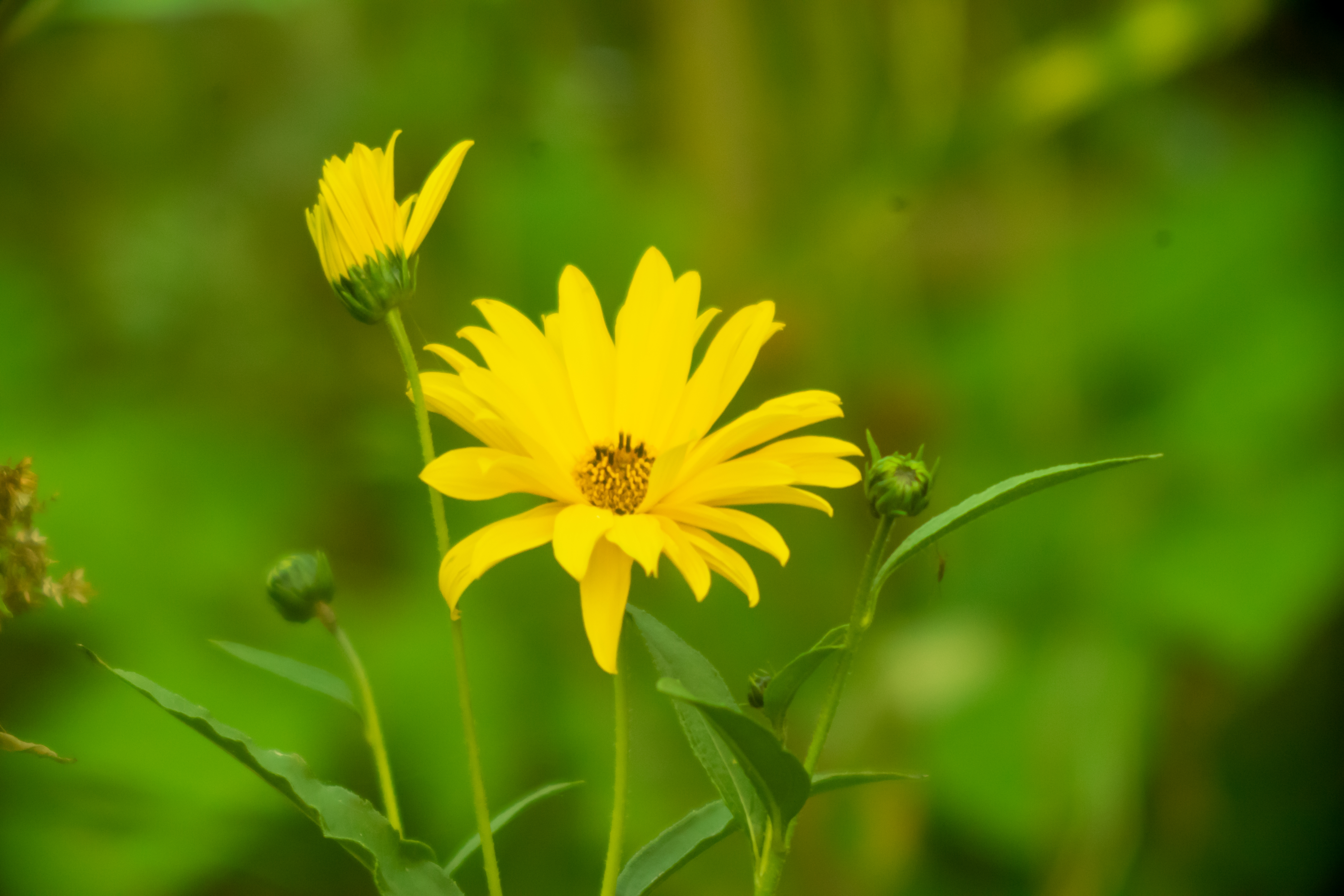
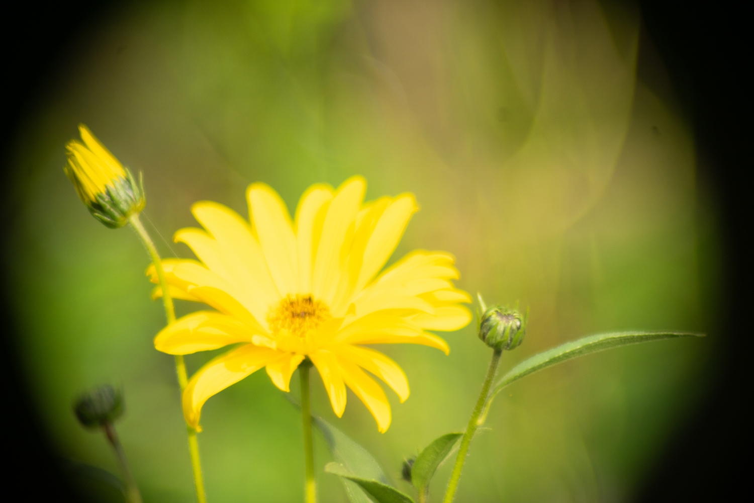
It was a race against the clock to make some pictures 1 hour before sunset. I made 2 paper disks one with a 40mm hole and one with 60mm. Put them right behind the lens. So the light conditions were bad! Iso 6400 and a lot of noise of course 60 of a second with no decent tripod mount yet.  But I want to know!! But I want to know!!


The results are way better (mechanical aperture still on the lens but wide open) I know now that it is possible. Still a lot of work to do.
The big question is, what is the advantage of making such a big heavy lens. My guess is that there is an advantage because of the diameter of the lens. There is a lot of light to catch on difficult circumstances. Maybe there is real Leica quality, maybe there is a great bokeh. It make no sense to make such a big lens with the same quality standards like all the other Leica lenses if the goal is to project something from a piece of paper on the wall. We will see. Things to do: Make more diameter aperture holes and test them on different distances from the lens. Make a sturdy tripod mount. Make a good lens hood. Coat the inside of the lens housing with black math paper. Make infinity pictures. Wait for more light

60mm

40mm |
|
| Back to top |
|
|
aidaho
Joined: 29 Apr 2018
Posts: 456
Location: Ukraine
|
| Posted: Mon Sep 23, 2019 8:50 pm Post subject: |
|
|
aidaho wrote:
| leonknook wrote: |
The big question is, what is the advantage of making such a big heavy lens. My guess is that there is an advantage because of the diameter of the lens. There is a lot of light to catch on difficult circumstances. Maybe there is real Leica quality, maybe there is a great bokeh. |
It's not a matter of advantage.
This lens is catching as much photons per sensor's cm² as any other (more compact) 400/4 out there.
Leica in question was likely designed to cover much bigger medium than FF, cue the humongous size.
_________________
https://www.flickr.com/photos/curry-hexagon/ |
|
| Back to top |
|
|
visualopsins
Joined: 05 Mar 2009
Posts: 10531
Location: California
Expire: 2025-04-11
|
| Posted: Mon Sep 23, 2019 11:38 pm Post subject: |
|
|
visualopsins wrote:
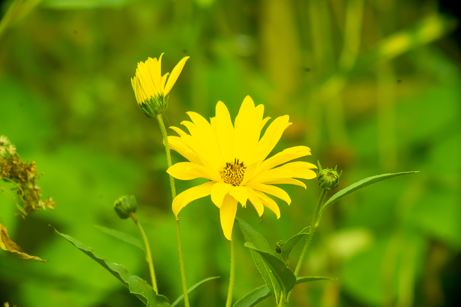
Hey I see dof change between those examples! 
| leonknook wrote: |
| IThings to do: Make more diameter aperture holes and test them on different distances from the lens. |
Farther away the size of aperture will be smaller for same dof as larger size closer to lens. Ha ha, now we can guess the secret! Apertures farther from lens can be smaller, i.e., faster operating and less expensive to make. 100mm max diameter diaphragm just behind lens may be best optically, but 50mm diameter placed closer to camera gives same f/#s.
_________________
☮☮☮☮☮☮☮☮☮☮☮☮☮☮☮☮☮☮☮☮☮☮☮☮☮☮☮☮☮☮☮☮ like attracts like! ☮☮☮☮☮☮☮☮☮☮☮☮☮☮☮☮☮☮☮☮☮☮☮☮☮☮☮☮☮☮☮☮
Cameras: Sony ILCE-7RM2, Spotmatics II, F, and ESII, Nikon P4
Lenses:
M42 Asahi Optical Co., Takumar 1:4 f=35mm, 1:2 f=58mm (Sonnar), 1:2.4 f=58mm (Heliar), 1:2.2 f=55mm (Gaussian), 1:2.8 f=105mm (Model I), 1:2.8/105 (Model II), 1:5.6/200, Tele-Takumar 1:5.6/200, 1:6.3/300, Macro-Takumar 1:4/50, Auto-Takumar 1:2.3 f=35, 1:1.8 f=55mm, 1:2.2 f=55mm, Super-TAKUMAR 1:3.5/28 (fat), 1:2/35 (Fat), 1:1.4/50 (8-element), Super-Multi-Coated Fisheye-TAKUMAR 1:4/17, Super-Multi-Coated TAKUMAR 1:4.5/20, 1:3.5/24, 1:3.5/28, 1:2/35, 1:3.5/35, 1:1.8/85, 1:1.9/85 1:2.8/105, 1:3.5/135, 1:2.5/135 (II), 1:4/150, 1:4/200, 1:4/300, 1:4.5/500, Super-Multi-Coated Macro-TAKUMAR 1:4/50, 1:4/100, Super-Multi-Coated Bellows-TAKUMAR 1:4/100, SMC TAKUMAR 1:1.4/50, 1:1.8/55
M42 Carl Zeiss Jena Flektogon 2.4/35
Contax Carl Zeiss Vario-Sonnar T* 28-70mm F3.5-4.5
Pentax K-mount SMC PENTAX ZOOM 1:3.5 35~105mm, SMC PENTAX ZOOM 1:4 45~125mm
Nikon Micro-NIKKOR-P-C Auto 1:3.5 f=55mm, NIKKOR-P Auto 105mm f/2.5 Pre-AI (Sonnar), Micro-NIKKOR 105mm 1:4 AI, NIKKOR AI-S 35-135mm f/3,5-4,5
Tamron SP 17mm f/3.5 (51B), Tamron SP 17mm f/3.5 (51BB), SP 500mm f/8 (55BB), SP 70-210mm f/3.5 (19AH)
Vivitar 100mm 1:2.8 MC 1:1 Macro Telephoto (Kiron)
|
|
| Back to top |
|
|
Teemō
Joined: 07 Apr 2016
Posts: 586
Location: Australia
|
| Posted: Wed Sep 25, 2019 3:32 pm Post subject: |
|
|
Teemō wrote:
Very nice result with the 40mm aperture! |
|
| Back to top |
|
|
|
|