Sansiro
Joined: 14 Jul 2016
Posts: 8
Location: Milano, Italy
|
 Posted: Mon Aug 01, 2016 5:20 pm Post subject: Jupiter-21M 200mm f/4 - Disassembling & Cleaning Guide Posted: Mon Aug 01, 2016 5:20 pm Post subject: Jupiter-21M 200mm f/4 - Disassembling & Cleaning Guide |
 |
|
Sansiro wrote:
After some fifteen years buried in a carton box down in my basement, this lens finally resurfaced to the light one month ago, when I decided to open one of the boxes still closed from the day I moved to Milano, back in 2001… It had been boxed because the aperture blades were lazy and sometimes stuck, and my intention was to fix it quite soon, but a son soon arrived, then another one, then a second moving, a job change… briefly, I even forgot about its existence.
After a quick check of its conditions I was seriously considering trashing it: stiff focusing, completely stuck aperture (both in auto and manual modes), heavy fungus growth on both front and rear elements, barrel corrosion and last but not least, an awful smell of mold.
Finally I decided to give it a try, after all such a lens is the perfect candidate for the experimentalist diyer: almost all the most common problem of an old MF lens in one go! And even in case of total failure, I would have learnt something useful.
A deep search on the internet didn’t result in any complete guide about disassembly and service of this lens, the best I could find was a partial (but very useful) disassembly guide about the aperture mechanism part:
http://www.pentaxforums.com/forums/114-maintenance-repair-articles/300843-jupiter-21m-issues-repaired.html
So I thought it could have been good to take out my old-cheap-digital camera and try to document what I was going to do. By the way, I apologize for the bad quality of the pictures, but I took them while working, keeping the camera by hands and without any other light source than the standard illumination of my workbench. To make things worse, it was late, very late in the night…
Here’s the whole story:
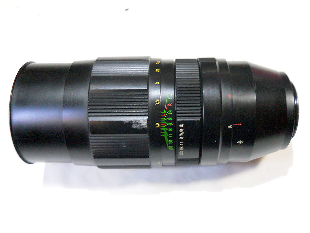
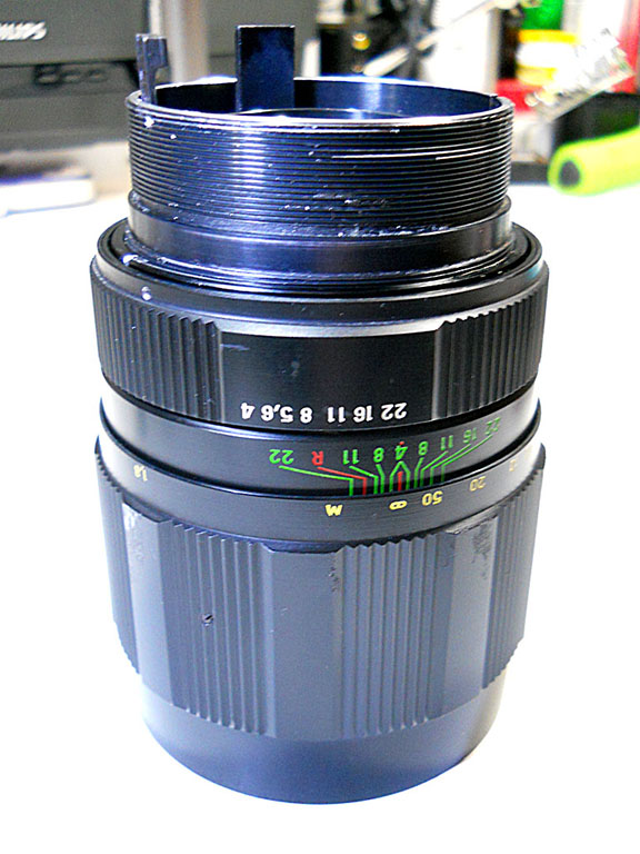
This is the lens. Here the only visible flaw is some barrel corrosion on the focusing ring. Actually I took most of the pictures while reassembling the lens, as the camera was charging batteries during most of the disassembly process.
Picture 1:

Now let's start the disassembly process.
Step 1 - Lens mounting and Auto-aperture mechanism
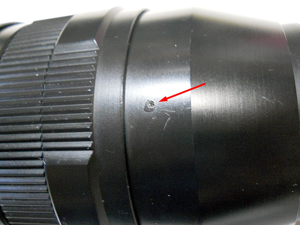
Relying on the guide by Mr. Helios 84-5 of pentaxforums.com, I started the disassembly from the back side. Firstly remove the rear conical-shaped barrel cover, the one sporting manufacturer’s logo and M/A switch reference line. There are two very small set-screws at opposite sides. You need a very small precision screwdriver here, between 0.5 and 0.8mm, not more. You don’t need to remove the set-screws, unscrew them just one full turn or a little more, until you feel you’re able to unscrew the cover:
Picture 2

Now unscrew the cover:
Picture 3

This is the lens with that cover off:
Picture 4

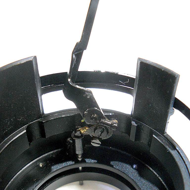
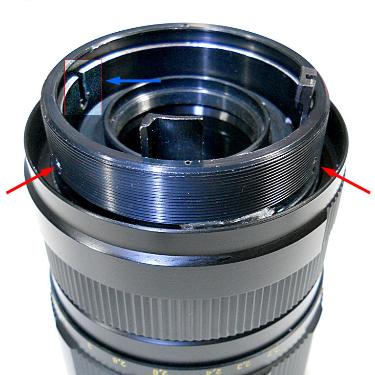
Now you can simply pull out the rear housing with the camera mount and the M/A switch mechanism. No need to take note about the position, there’s a screw on the housing whose protruding head will fit into a slot cut on the ring still hidden inside the threaded part and doesn’t allow any other mounting position. Here’s the rear housing:
Picture 5

The blue arrow indicates the Auto-aperture lever, which must be straight. This is apparently a source of problems in many lenses (not in mine) as it has a way to get bent and thus interfering with other parts of the lens. In such a case, this is the time to straight it back and to fix this problem.
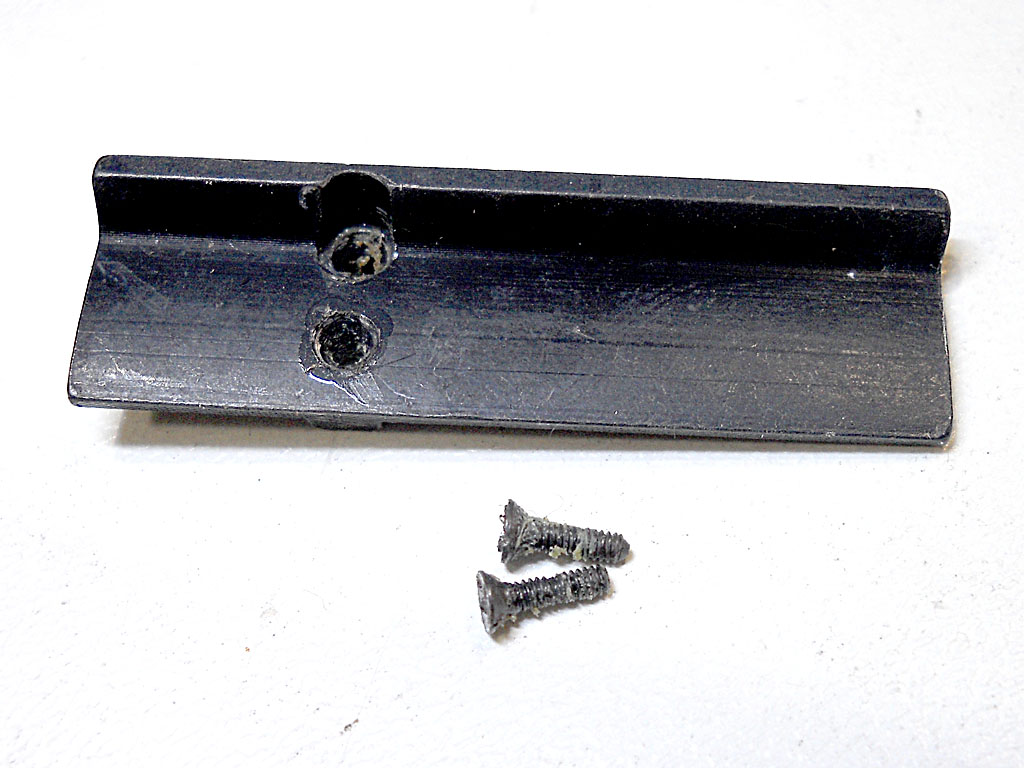
The red arrow indicates the cover plate you have to remove in case you need to get access to the lever mechanism:
Picture 6

By the way, I’ve read some comments in the internet about a great improvement of this lens’ performance in terms of contrast that can be obtained just covering this plate with some light-absorbing material (i.e. a dull black fabric, or maybe velvet…), If you want to try this easy modification on your lens, that’s the right time.
In the next photo you can see the Auto-aperture mechanism, with the actuator pin and the return springs. There are apparently two different versions of this mechanism. The one documented in the Pentaxforums tutorial can be easily disassembled as a whole unit from the housing because it’s held in position by two screws set from outside the housing. Mine was different, the two mounting screws were set from the inside, so the mechanism can’t be disassembled as a whole unit but it must be taken fully apart in order to get access to the mounting screws heads. And this was what I was considering to do because this mechanism was completely stuck by the rust. Yes, rust. Levers and pivots are apparently made of plain iron, and they easily get rust if not used for a while and stored in a humid place.
Instead of taking the whole mechanism apart, I tried before to apply some WD40… It took a lot of it (and the time to let it penetrate) before I could little by little have the mechanism moving satisfactory. I know WD40 is quite a crude approach, a better job would require complete mechanism disassemble, careful cleaning and deoxidation of all the parts, lubing and reassembling… but since WD40 worked it out quite fine, maybe I’ll do the correct job the next time 
Picture 7

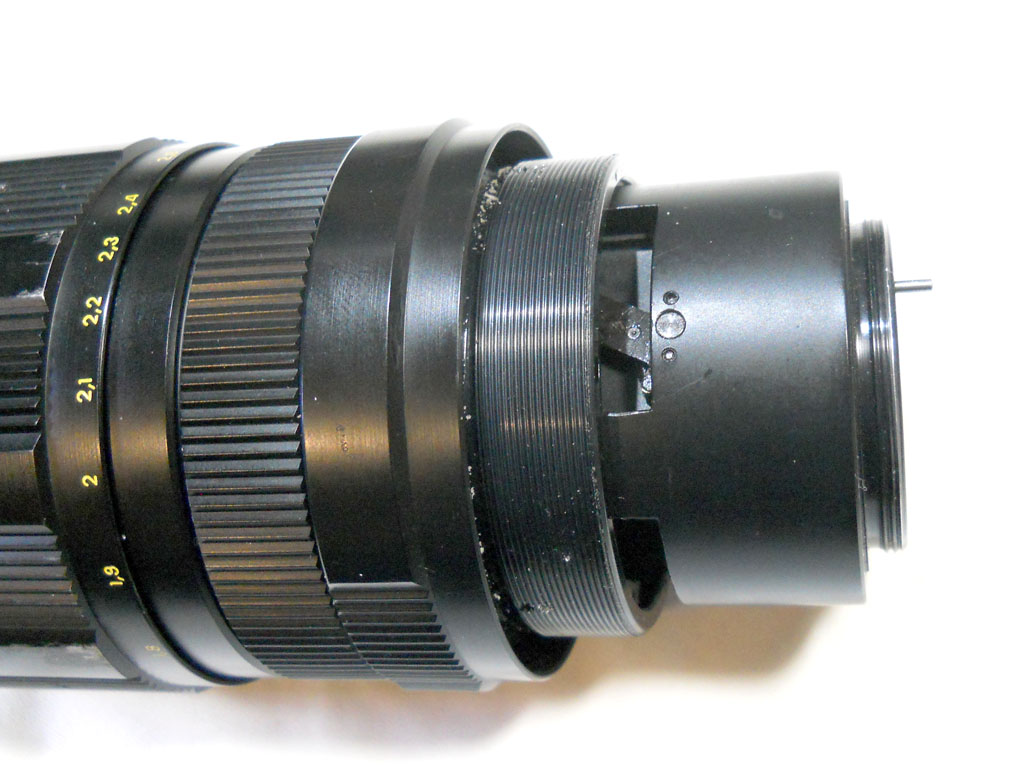
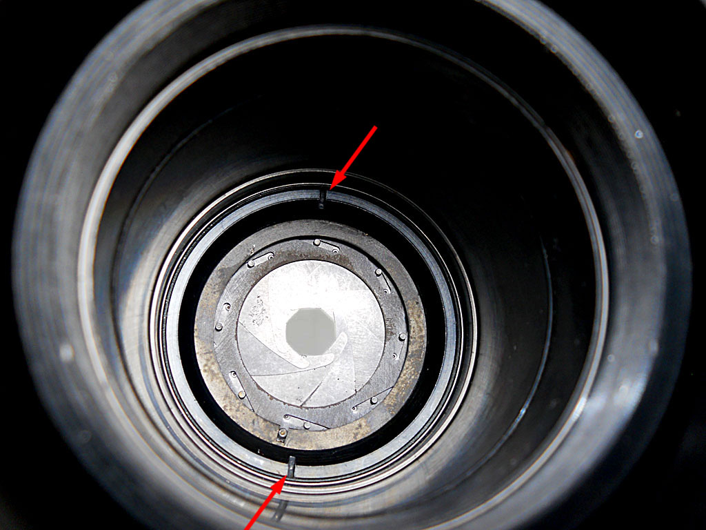
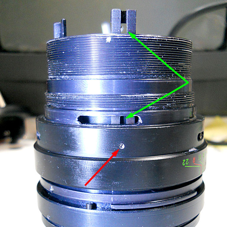
This is the back of the lens, without the parts removed so far. The red arrow points to the aperture stop-down lever (the lever that actually closes the iris to the selected aperture) in the exact point where the Auto-aperture lever tip should contact it once in place.
Note that you have now access to rear lens group, indicated by the green arrows. You can already remove it, or choose to do it in a later step when taking care of the optical part, or even leave it in place if you don’t need to clean it or to gain access to the iris group. I took it out at this point, but we will see it later on.
Picture 8

Step 2 - Manual/Automatic aperture selector
It’s now time to remove the threaded ring where the conical cover of step 1 was screwed on. There are 3 tiny set-screws positioned at 120° from each other, two are indicated by the red arrows on the next pic at 4 o’clock and 8 o’clock, the third (here not visible) is at 12 o’clock. As before, don’t remove them, just unscrew about 1 turn and then you should be able to unscrew this threaded ring, by hands if it’s not too tight or with the help of a lens spanner wrench or other suitable tool (there are two holes in its edge). Note the “enlightened” square indicated by the blue arrow at top left: this is the slot where the position-setting screw head of the M/A mechanism housing (step 1) goes in.
Picture 9

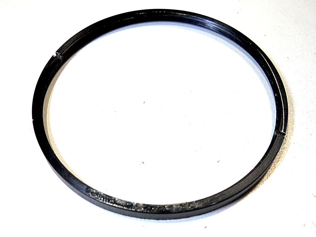
This is the threaded ring with the spanner holes clearly visible:
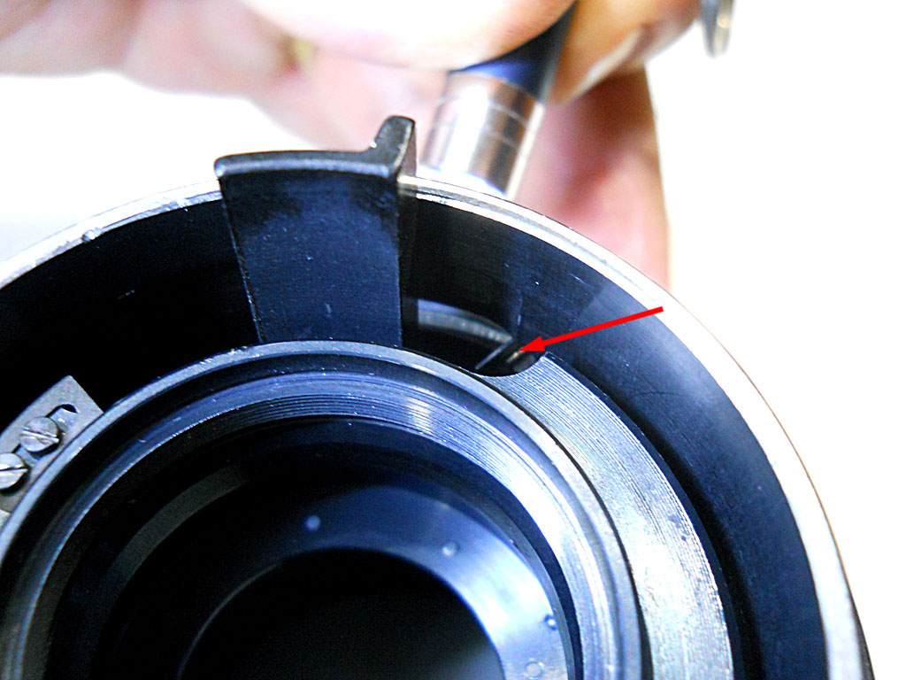
Picture 10

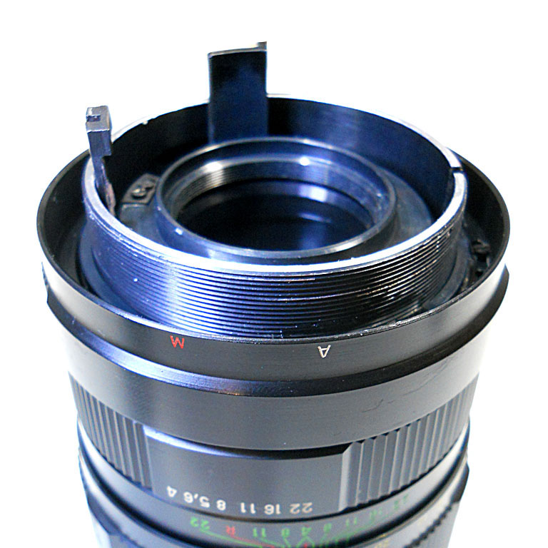
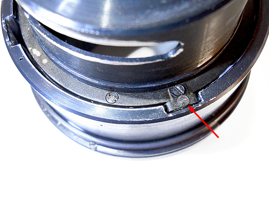
Here’s the lens once removed that ring. You clearly see the aperture stop-down lever at about 12 o’clock, the reference slot mentioned above at 3 o’clock and another protruding lever at 9 o’clock. This is the lever that transfers the preselected aperture information from the aperture ring to the iris group, but we will see this later. Now it’s time to remove the M/A selector, or switch, as you prefer.
Picture 11

As you can see watching inside from the top, there are three screws fixing the M/A switch outer ring to its inner part. Note that the screws are not passing through circular holes but through elongated slots, these are made to allow adjustment of the “A” and “M” markings position against the red reference line on the conical cover. If they were correctly aligned before, I suggest you to scribe a reference mark to help realign it when reassembling. I didn’t, but used the markings left by the screw’s heads instead, and l was lucky enough to perfectly center it while reassembling.
Picture 12

And voilà, the M/A selector ring (external part) with the three screws:
Picture 13

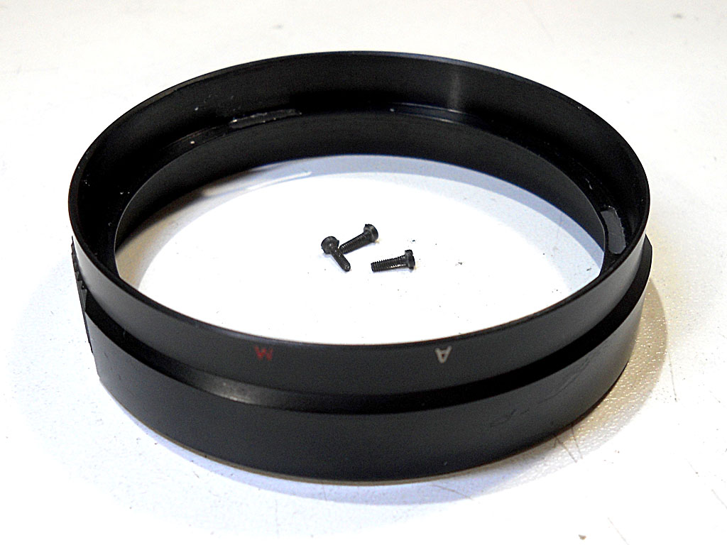
This is nothing but a “decorative” rim, with knurling to better grasp it and the A and M reference letters. The actual selector ring is the internal one, where the external ring was screwed on:
Picture 14

Here we can see the actual selector ring, pointed by the blue arrow, and a locking ring, with two slots for a spanner wrench, pointed by the red arrow. This locking ring keeps the selector ring down into place, and must be unscrewed at first. It is “glued” to the threaded part with some threadlocker compound, so it may be quite stiff to unscrew without a good spanner. When reassembling it, don’t forget to re-apply some threadlocker (not a strong one, and not too much, just a few tiny droplets) and take care to screw it in until it almost touches the M/A selector ring (that must be already correctly seated) with just a minimal of friction, in order to keep the selector ring in place leaving it free to turn in both directions.
Here’s the locking ring removed:
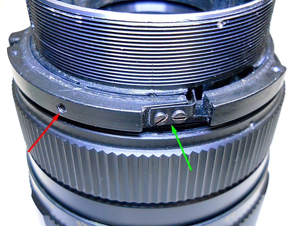
Picture 15

And here is the A/M selector ring, still in place, with the actuator tab and its two mounting screws (green arrow) and the set screw to adjust the pressure to the click-stop ball (red arrow):
Picture 16

As you can see in the next photo, the actuator tab, pointed by the arrow, protrudes inside the lens body through a slot beside the stop-down lever. The Auto-aperture lever seen in step 1 must sit between the two, so when the M/A switch is in Auto position (actuator tab fully to the right in this photo), the stop-down lever is actuated only by the Auto-aperture lever (that is in turn actuated by the usual pin in the camera mount). When the M/A switch is turn in Manual position (fully to the left in this photo) it pushes both the Auto-aperture lever and the stop-down lever fully to the left, causing the iris to close to the pre-selected aperture value. Simple and effective, if correctly machined and assembled… that is not always the case, apparently.
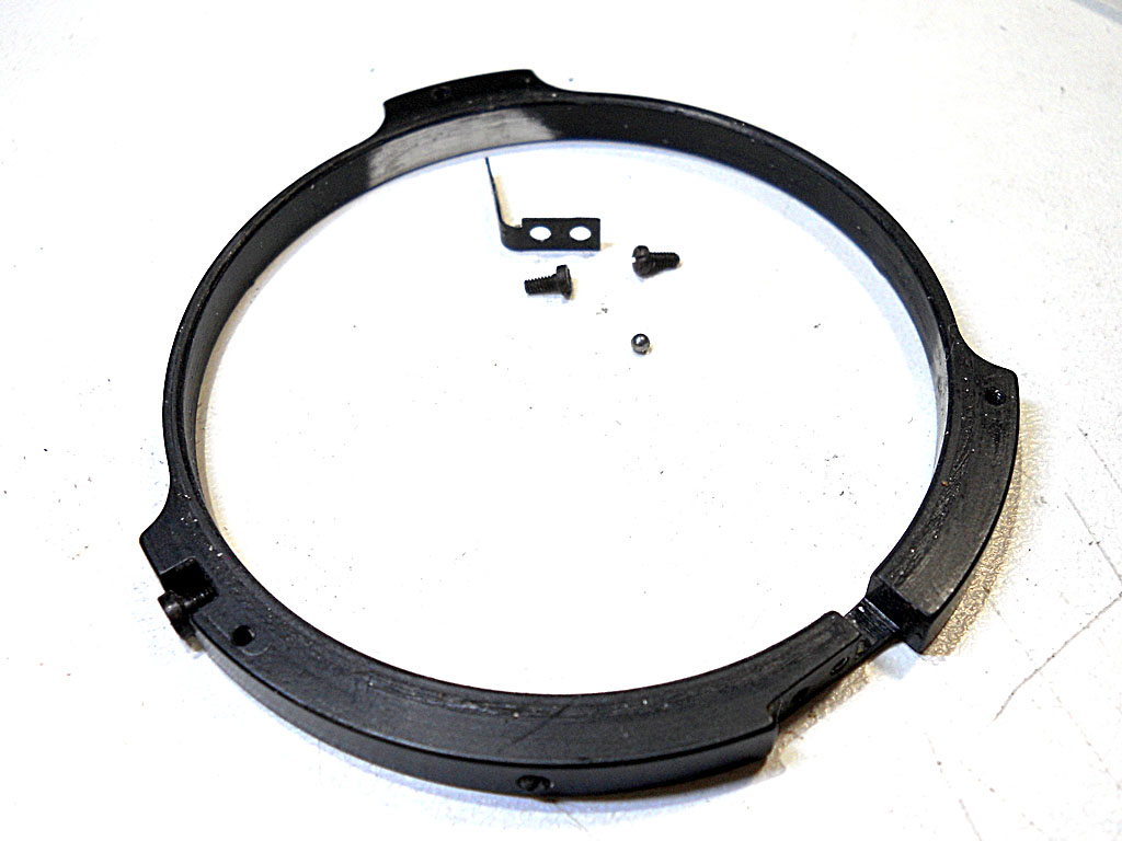
Picture 17

To remove the M/A selector ring you must first unscrew the actuator tab (two screws) and release the pressure to the click-stop ball (red arrow in picture 16) then simply slide out the ring. Be careful not to lose the ball! And also remember it when reassembling. Here’s the ring, tab, screws and ball:
Picture 18

Step 3 - Optical groups
Now, before going on with the aperture selector ring and the iris mechanism, we must point our attention to the optical groups. In fact, the iris group sits between the middle and the rear optical groups (this lens is a 4 elements in 3 groups), so we have to “clear the path” if we want to get access to the iris.
Since we are already working on the rear side, let’s start from here, unless you have already removed the rear lens group at the end of step 1. In case you didn’t, do it now. This is the rear lens group once removed:
Picture 19

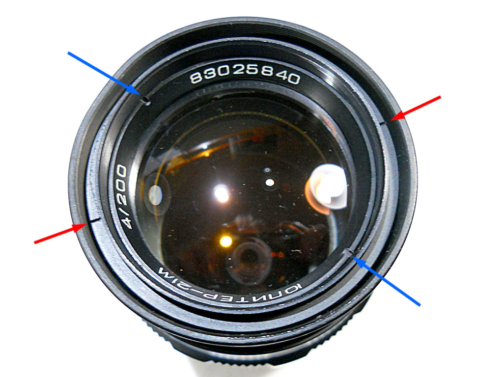
It’s now time to turn the lens upside-down and have a look to the front side:
Picture 20

Oh yes, I forgot to mention that this lens has also a bump on the sunshade. I simply don’t care about it, it’s only a minor aesthetic issue and I was not repairing this lens to trade it.
So don’t watch to the bump but watch the arrows instead: the blue arrows show the inner ring, the first to be unscrewed. Unscrewing this ring will loose the front and middle lens groups, along with a spacer ring in the between, in one turn, so I suggest you to operate this way: unscrew and take out the ring, than wear white cotton gloves (or make use of a clean soft white cloth), cap the front of the lens with a hand, carefully flip the lens upside down and let the elements softly land in your hand. Have a look at the orientation of the spacer ring and lay everything on your workbench. Here they are, left to right: outer ring, front element, spacer ring, middle group.
Picture 21

Have a closer look to the spacer ring. As you can see it’s slightly beveled internally, and its correct orientation is with the wider end towards the front element:
Picture 22

Now you can clean your lens elements, defungus them, or whatever else you need to do them.
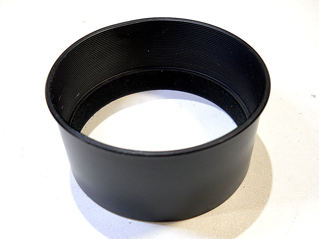
The outer retaining ring (red arrows in picture 20) is retaining the sunshade, simply unscrew it and slide out the sunshade:
Picture 23
Picture 24

This is how the front of lens appears now:
Picture 25

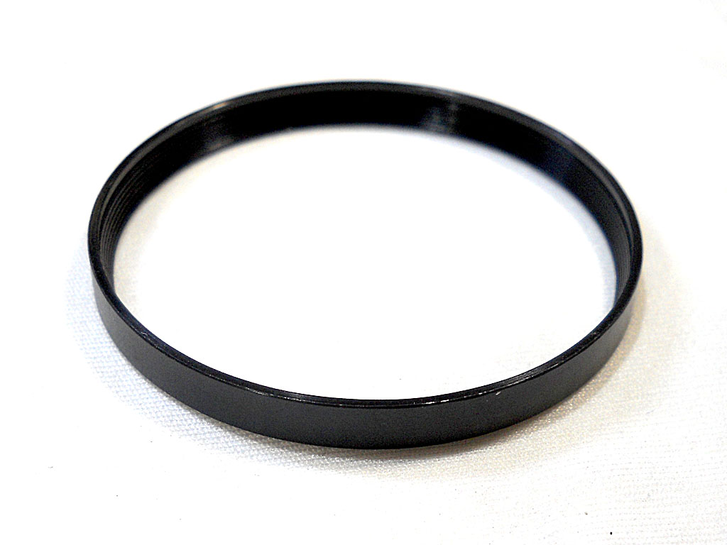
Here’s yet another ring making its appearance. Or maybe I’ll better call it a sleeve. Call it as you like, but in both cases insert your spanner into the slots indicated by the arrow and unscrew it:
Picture 26

Step 4 - Diaphragm aperture ring and mechanism
Now you can finally begin to have a glimpse at the focusing helicoids. If your lens focus is just somehow stiff but not really stuck, and there’s no grit or metal debris mixed to the old grease, you may already be able to pour some lubricant and/or new grease to have it rotate smoothly. In my lens there was a plenty of metal grit and debris. Apparently nobody at the factory took the time to give its parts even a half-a-second compressed-air blow after milling them! So if your lens has never been serviced before, my advice is to always have a complete helicoids disassemble, deep cleaning and accurate re-greasing. I will cover helicoids service in a next step, so right now take your smallest screwdriver and unscrew (again, not completely) the two opposite set-screws indicated by the arrow:
Picture 27

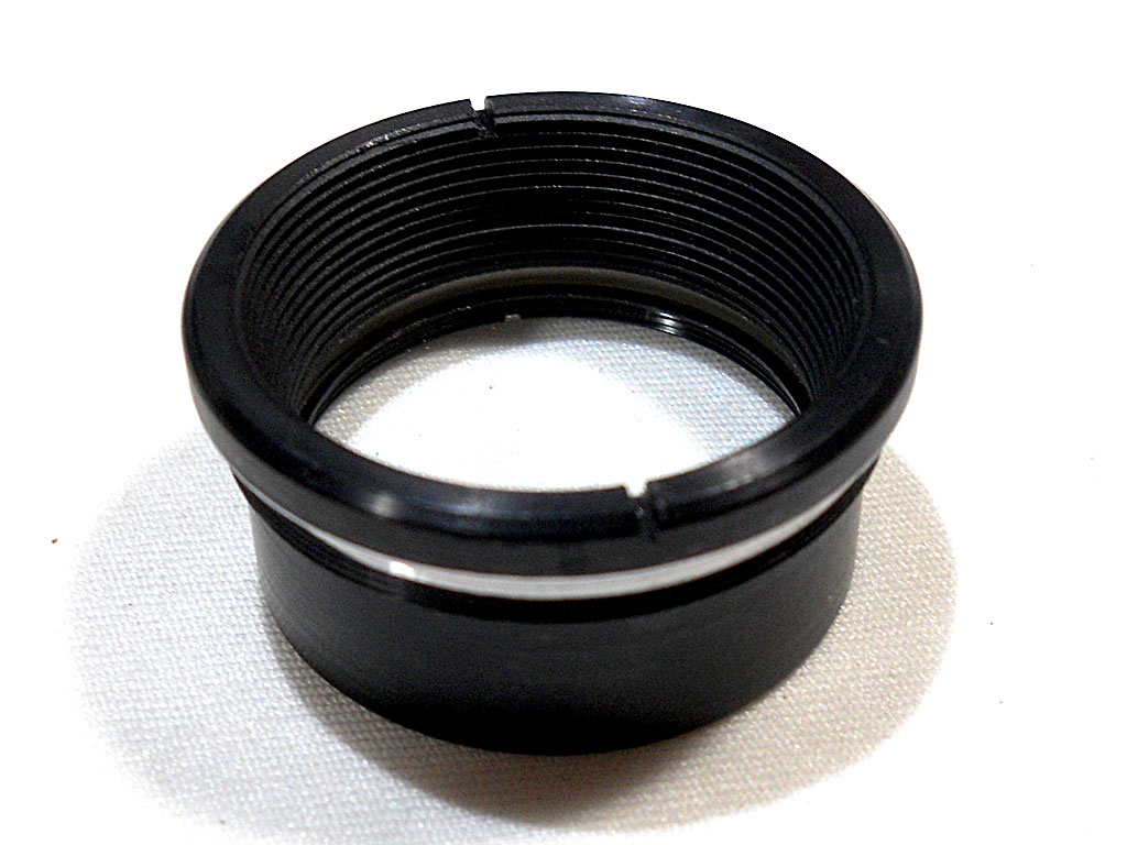
This will allows you to unscrew and remove the front threaded sleeve, where the lens elements were sitting inside. It is shaped like a funnel:
Picture 28

The removal of this sleeve reveals… another retaining ring, right above the iris mechanism:
Picture 29

Remove this as well and set it apart:
Picture 30

Now, to be able to take the iris mechanism out of the lens barrel, there’s some more work to do from the rear side. Here is the lens as it appears now:
Picture 31

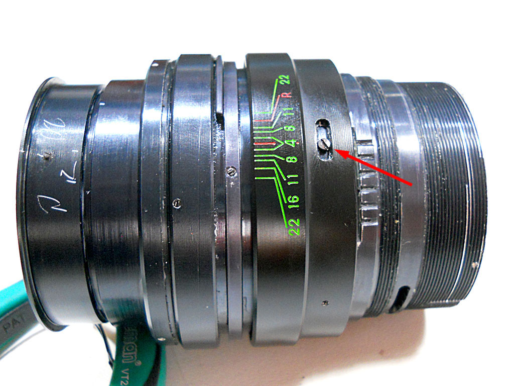
Let’s have a closer look to the aperture pre-selection ring. It is retained by three set-screws, like this one:
Picture 32

Remove the three set-screws and slide out the ring:
Picture 33

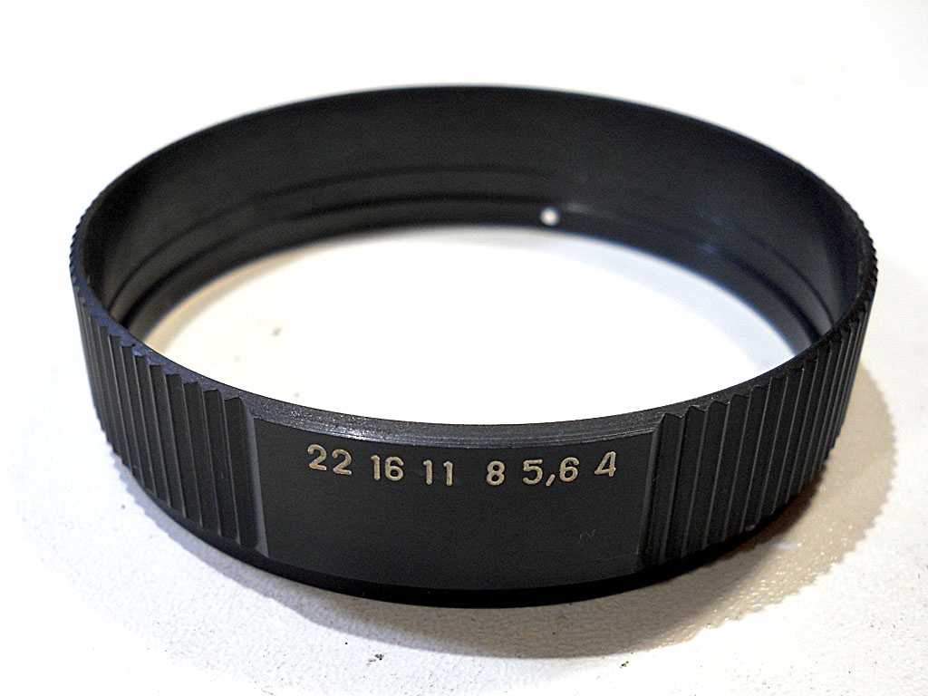
As it was the case for the M/A selector, this ring is just the external decorative part, and the actual working part is hidden below:
Picture 34

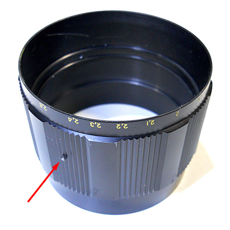
No difference with regards to the focusing ring: undo (not remove) three set screws, slide the external ring out, and reveal the actual focusing ring:
Picture 35

Now, remove the aperture pre-selector-ring retaining ring (sorry for the repetition, but that’s what they are: a ring retaining another one. I would be more than happy if some mother-language English speaker would like to revise this text…).
This retainer is locked by some kind of thread-locking compound as we saw for the M/A selector retainer. Remember it while reassembling, and take care about its correct adjustment, in order to keep the pre-selection ring firmly in place still leaving it free to rotate right and left.
Picture 36

Here it is:
Picture 37

And finally start working on the aperture pre-selector: before heading your hand to the nearest screwdriver, have a close look to the ring. You will notice three pairs of screws, but only one of the pairs (red arrows) show the back of an internal pin in the between. These screws are also slightly larger in my lens. The other two couple of screws (green arrows) are there to fix the blade-spring of the click-stop balls. There are two click-stop balls because this lens has a half-stop click diaphragm ring. Using two separate click-stop balls working on two slightly shifted series of grooves allows realizing such a mechanism without the need of high-precision tools and avoiding the use of microscopic balls. Don’t touch the click-stop screws otherwise you will likely lose those balls.
Picture 38

Unscrew only the two red-arrow screws and then remove the pin and the ring:
Picture 39

In the following pictures we can see how the aperture pre-selector works: The pin connected to the pre-selector ring fits into the slot on the pre-selector lever as indicated by the green arrows. The pre-selector lever is elongated because the pre-selector ring (and pin) is steady with respect to the lens mounting when focusing the lens, while the iris group, which sits between the lens elements, moves back and forth. The pre-selection lever, as we will see very soon, is connected to the iris mechanism casing and makes it rotate right and left along with the rotation of the pre-selection ring. The aperture stop-down lever (actuated by the Auto-aperture lever) actuates a pin inside the iris mechanism casing that actually stops down the blades. How much the blades are stopped-down, depends on the angular position of the casing: when it is fully against the stop-down lever, the blades are allowed to close the most, when it is at the furthest angle from the stop-down lever, the blades are not actuated at all.
Picture 40

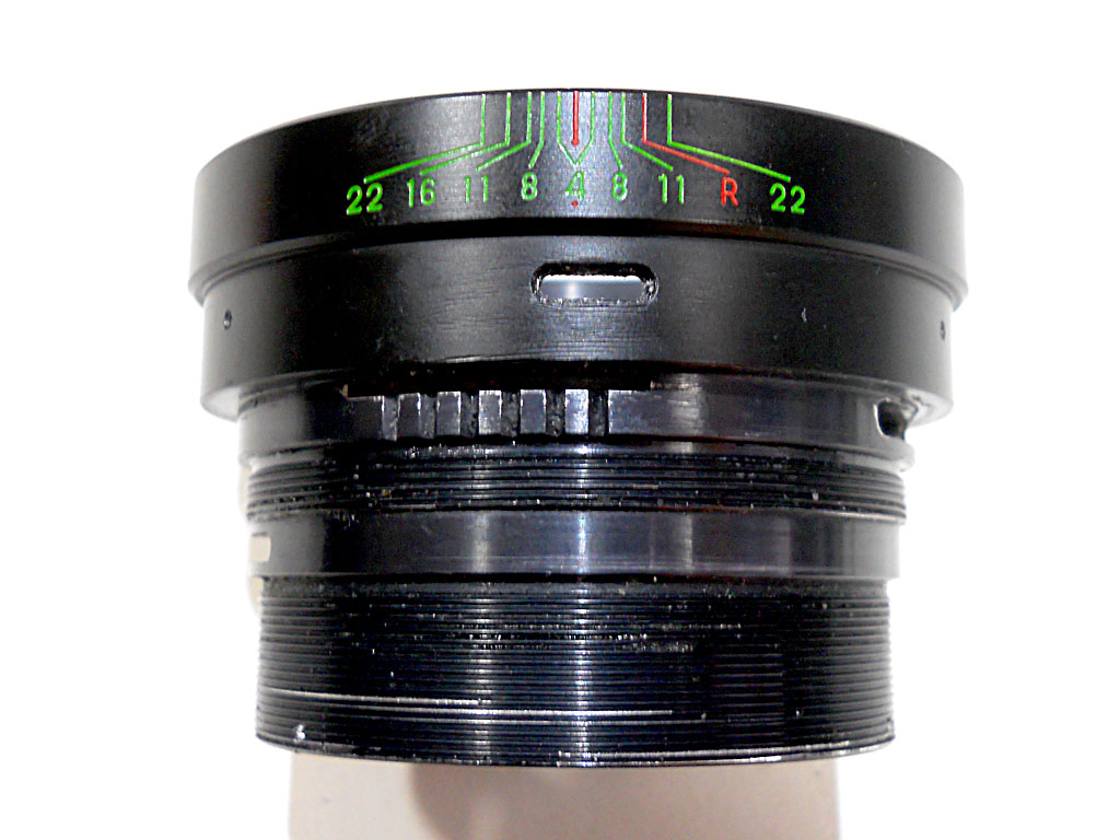
Anyway, to go further deep in our “dissection” we have now to remove the ring with the diaphragm reference line and the depth-of-field markings. To do this, unscrew the three set-screws one of wich is marked by the red arrow in the previous picture, as well as the screw marked in the next picture:
Picture 41

Slide the ring out:
Picture 42

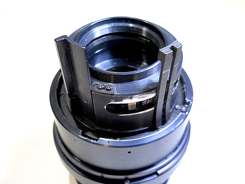
So we can now have a look to the diaphragm levers, and maybe beginning to make an idea about why is this lens so damn heavy… have you never seen the levers inside a Japanese lens?
Picture 43

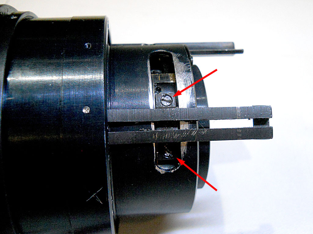
Now remove these two screws:
Picture 44

And the pre-selection lever:
Picture 45

These two screws were set with threadlocker in my lens, and I could not unscrew them at the beginning. You may need to either dissolve the threadlocker with a suitable chemical (maybe acetone?) or, as I did, heat the part with a hot-air gun. Again, remember to re-apply threadlocker when reassembly.
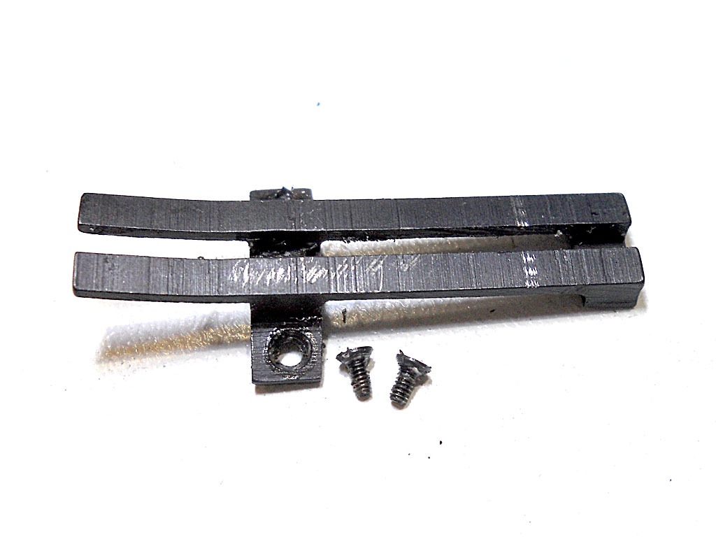
Now you should remove the stop-down lever:
Picture 46

Again two screws, again set with threadlocker, as you can see:
Picture 47

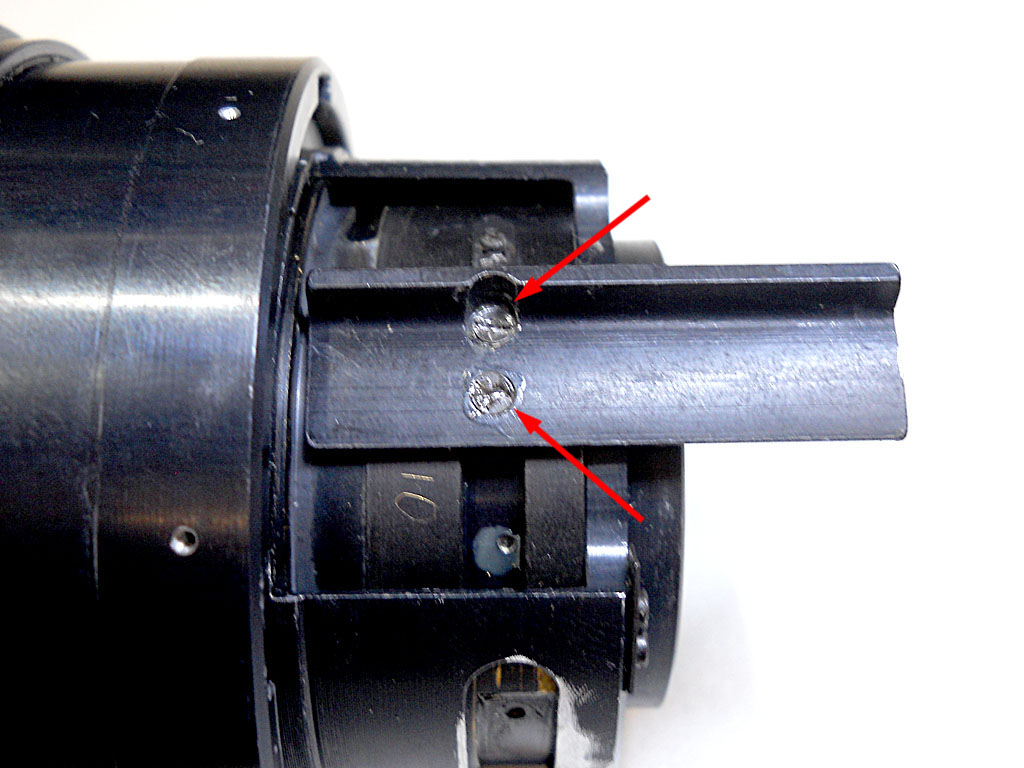
Finally the iris group is free to fall from inside the lens barrel, directly to your hands. Take note about the mounting position of the levers on the iris group casing and of the group itself inside the lens barrel.
This is where the pre-selection lever is screwed:
Picture 48

Here is where the stop-down lever is screwed:
Picture 49

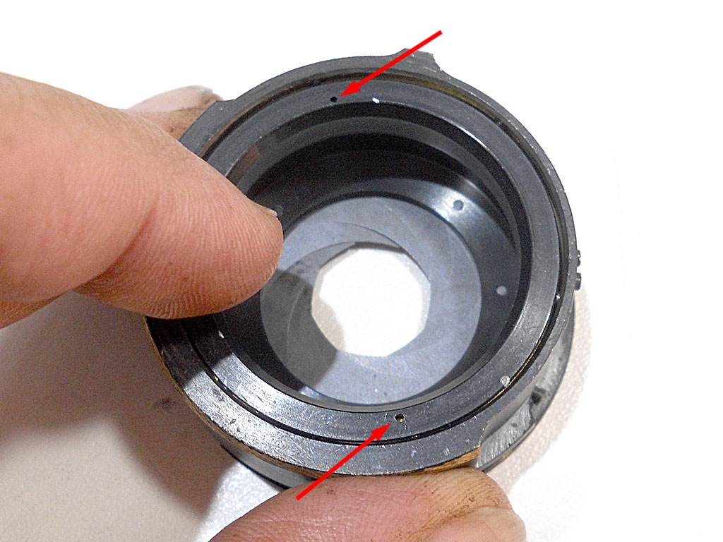
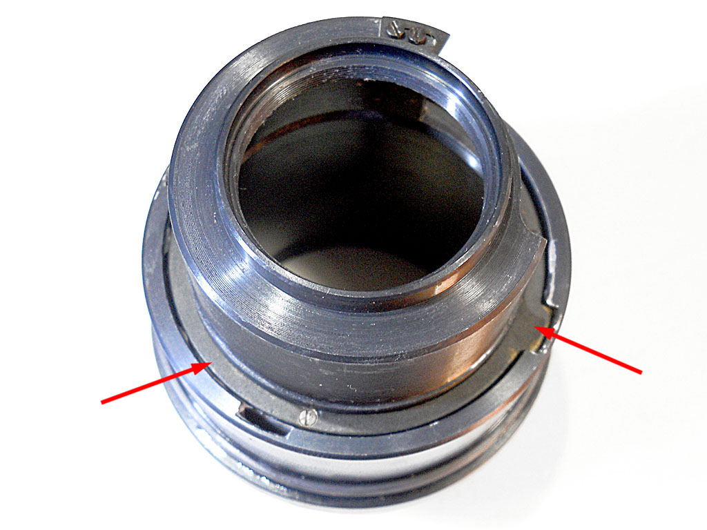
The face you can see here, with the blade-pivot elongated slots is the front-side face.
Picture 50

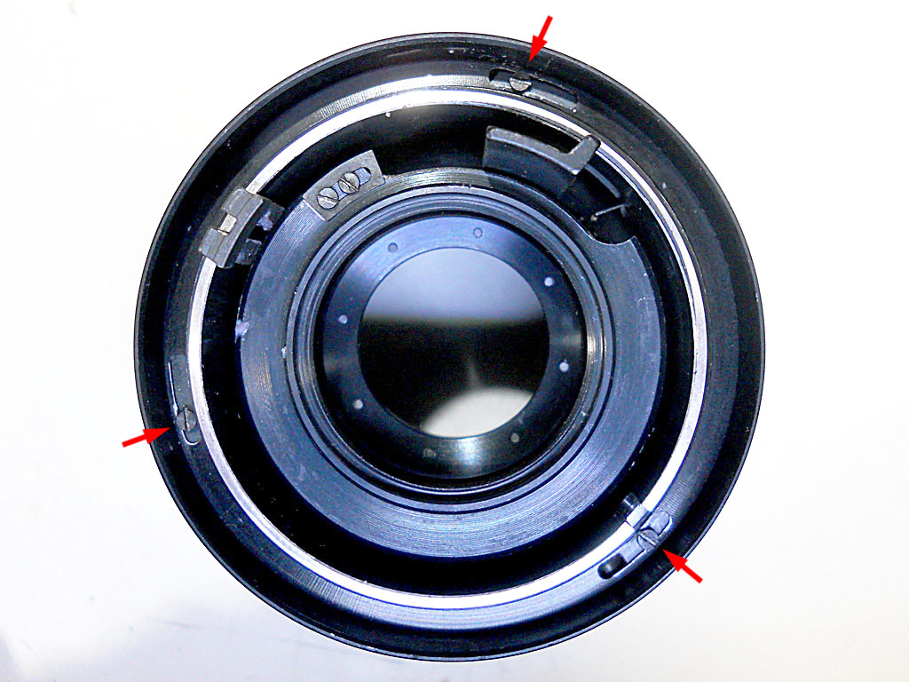
The other side, with the blades retaining ring (indicated by the two arrows) faces the back side.
Picture 51

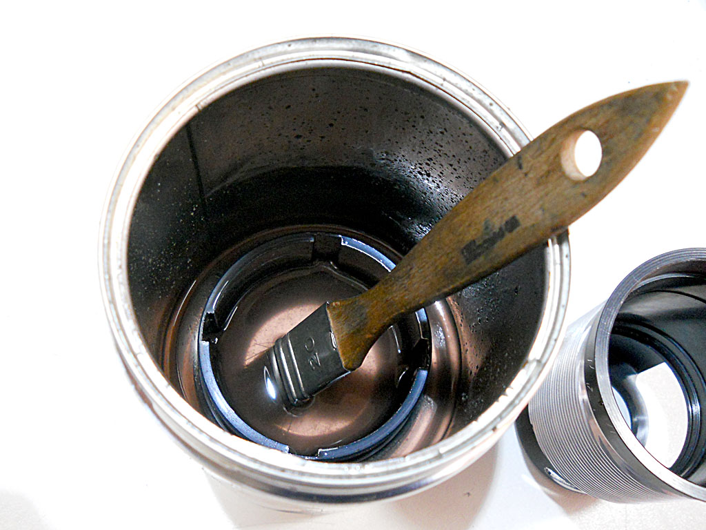
Unscrewing this retaining ring will leave you with all the blades free on your workbench. Although I’ve already serviced several other iris groups, or maybe because of it, I try to avoid it whenever possible.
If the blades of your lens are oily or otherwise dirty, the construction of this diaphragm mechanism may allows you to clean them without disassembling the group: just drop it in a jar filled with… what you normally use to clean iris blades, let it soak for some time, help the cleaning process with some manual iris open-close sequences or with the use of a very soft brush if needed, dry it with careful use of compress air and then test the functionality. If you are lucky, it should work perfectly, without the need for any lubrication. In case it doesn’t, you may try to put an extremely tiny amount of watchmaker oil (gun oil or sewing machines oil are also both good for this purpose) on each one of the blade pivots (on the retaining ring side). If it’s still not working well, you would probably need to disassemble the mechanism… I didn’t had to do it, so I have no pictures to show you, but it’s not very different from any other iris group you can find carefully explained on the internet. Also, If you have disassembled your lens down to this point, you surely have the skills to do it the right way.
If you remember the beginning of this long story, I once boxed this lens because the iris blades were lazy, and sometimes they even stuck. In 99% of the cases this problem is caused by oily blades or thickened lubricant on the blade pivots. To my surprise the blades of my lens were absolutely dry and clean, as well as the pivots. The problem was clearly somewhere else.
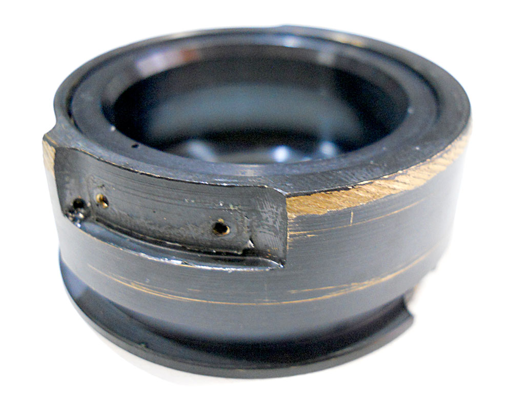
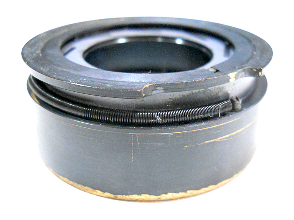
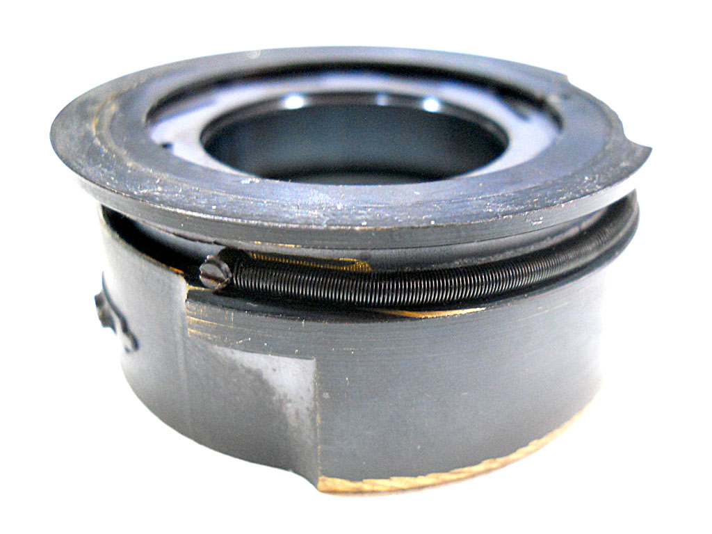
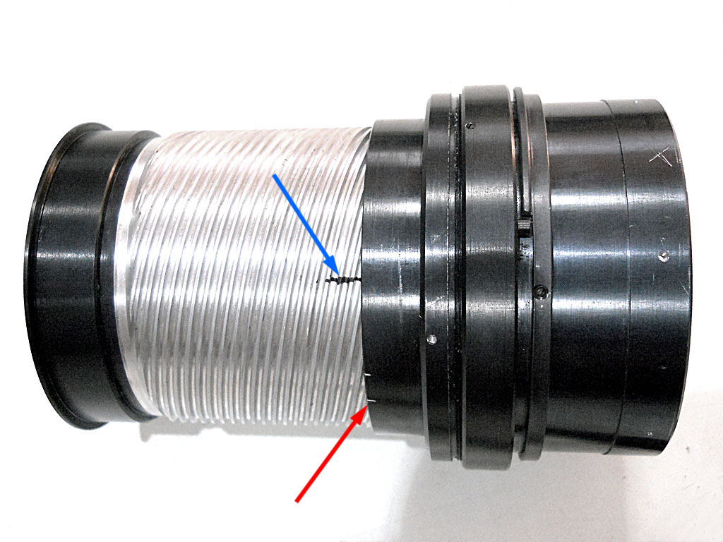
Actually, this was the cause:
Picture 52

Picture 53

In these two pictures you can see there’s a long and thin spring running around the iris casing circumference. This is the blades return spring: it is connected at one end to the outer casing and at the other end to the inner barrel, which moves the blades, so that when the action of the stop-down lever to the blades ceases, the blades suddenly snaps back wide open under the return action of this spring.
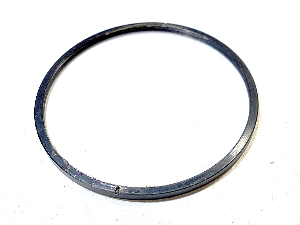
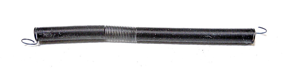
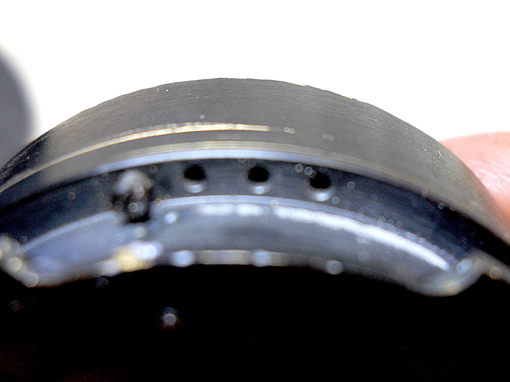
Now have a closer look to the spring:
Picture 54

As you can see the central zone is clearly weakened, and this reflects negatively to the entire spring action that was actually definitely “tired” with almost no more than a very feeble recall action. Practically speaking, you press the camera button, the blades closes at the selected aperture, but after the shot is done they simply don’t reopen, or they do it very slowly.
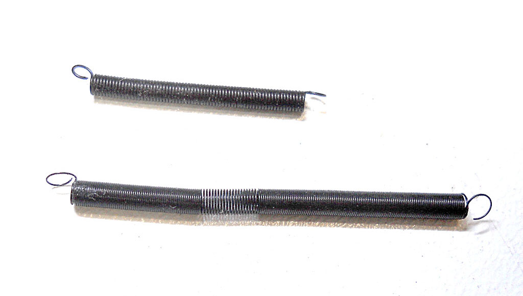
I tried to find a suitable replacement, but the only one I could find in my drawers was this (the upper spring):
Picture 55

That is way too short and stronger than the original spring.
I gave it a try but the iris action resulted to be too much contrasted, so that the actuator pin on the lens mounting would have been too hard to be pushed-in by almost any camera.
Since I couldn’t easily locate a suitable spare even the day after, asking to a pair of local shop, and didn’t want to leave all the lens’ parts rattling around my workbench for too long, I decided to cut the old spring, remove the weakened part and use the remaining part (almost half the length of the original spring). Fortunately, the screw fixing the spring at the iris group casing is adjustable. Meaning that there are four threaded holes where it can be screwed in, and it was originally screwed into the furthest one:
Picture 56
Definitely missed the focus, I’m sorry, but you can still recognize the four holes and the adjustable screw. The spring attaches to the screw and run clockwise around the casing as seen in the photo. So I moved the screw to the rightmost hole, reinstalled the “shortened” spring… and yes, it worked! I’m not sure about the reliability of such a repair, because I suspect the spring will go weakening again very soon, but at least I will have the time to look for a spare, and maybe to use this lens for some good shots these holidays.
Step 5 - Focusing helicoids
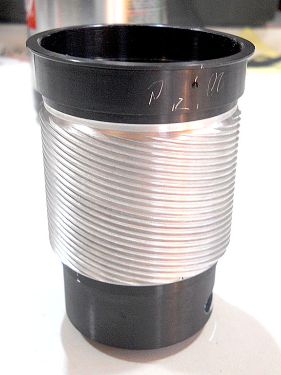
What we have now on the bench is just the focus helicoids group:
Picture 57

I already gave it a quick clean before taking this photo, as there was too much metal grit on it to even stay on my bench.
Now you must pay attention not to touch anything may let you lose infinity focus, or at least to take note of any mounting position and maybe scribe reference marks where needed.
Watching the helicoids from the rear side, we can notice this ring:
Picture 58

This is the device causing the multi-thread helicoids to move only back and forth (in and out) and not to rotate when the external ring (focusing ring) is rotated. It has two tabs running into two grooves of the outer ring, but one of the two tabs is mounted by two screws (don’t touch them) while the other is part of the ring. It is mounted by three non-evenly spaced screws, so you can’t miss its right position while reassembling, but you better mark with a felt-tip pen or a scriber the groove where the screw-mounted tab goes in:
Picture 59

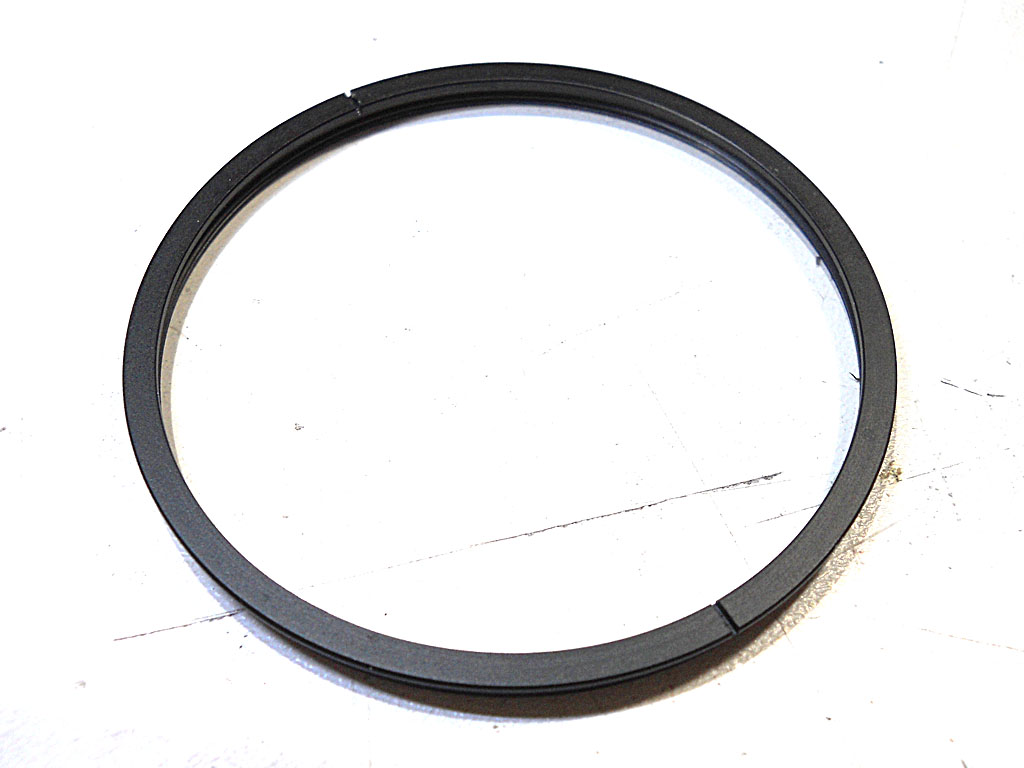
Here’s the ring:
Picture 60

Once you removed it, you are finally allowed to completely extract the focusing helicoids, but before doing it, keep a felt-tip thin marker at hand and start extracting it little by little, in order to be able to mark on both male and female helicoids the exact position where it gets free. This will allows you to remount it in the very same position after cleaning and re-greasing, and not to lose the infinity focus:
Picture 61
Here you see the line in the male helicoids already past the scribed reference in the female part, because I took the photo after cleaning and I gave the helicoids a slight turn to keep the parts in place while taking the photo. I used an already-scribed reference mark (red arrow), probably scribed in the factory, and just added my felt-tip mark (blue arrow) at the exact point the male helicoids went free.
So you are at the last step. Just clean thoroughly the two helicoids parts:
Picture 62

It’s so nice when it’s clean:
Picture 63

Re-grease the helicoids, and start reassembling everything, perhaps helping you by reading this guide backwards: :sdrawkcab ediug siht gnidaer yb uoy…
Enjoy!
© Davide Cavallaro – 2016 |
|