| View previous topic :: View next topic |
| Author |
Message |
scsambrook


Joined: 29 Mar 2009
Posts: 2167
Location: Glasgow Scotland
Expire: 2011-11-18
|
 Posted: Wed Jul 23, 2014 2:55 pm Post subject: Posted: Wed Jul 23, 2014 2:55 pm Post subject: |
 |
|
scsambrook wrote:
Okay - let me get this clear . . . the edges of the frame are less sharp than the centre ? Is that correct? And going by the lack of depth of field, the aperture must have been pretty wide open? So . . . is this fall-off in sharpness at wide apertures unusual? It doesn't look too bad to me. 
_________________
Stephen
Equipment: Pentax DSLR for casual shooting, Lumix G1 and Fuji XE-1 for playing with old lenses, and Leica M8 because I still like the optical rangefinder system. |
|
| Back to top |
|
 |
ZoneV
Joined: 09 Nov 2009
Posts: 1633
Location: Germany
Expire: 2011-12-02
|
| Posted: Wed Jul 23, 2014 3:03 pm Post subject: |
|
|
ZoneV wrote:
Probably there is a big sample variation - on these images the borders looks better.
https://www.flickr.com/photos/clwongwilliam/8118689939/sizes/o/
https://www.flickr.com/photos/belmoniaco/13966650819/sizes/k/
https://www.flickr.com/photos/shunsuke_onji/8545250094/sizes/o/
https://www.flickr.com/photos/clwongwilliam/8536361549/sizes/o/
https://www.flickr.com/photos/104852879@N08/10176836466/sizes/o/
https://www.flickr.com/photos/bk_avocado/4934894820/sizes/o/
Regarding the MTF curves from manufacturers - one does not know wheter the published MTF curves are typical, or the best hand optimized result. Or only the theoretical MTF the design software gives - without all production tolerances. One of the several reasons why I recommend not to compare MTF curves from different ressources.
Softer edges is exactly what I see in the MTF curves for the Sony STF 135
_________________
Camera modification, repair and DIY - some links to look through: http://www.4photos.de/camera-diy/index-en.html
I AM A LENS NERD!
Epis, Elmaron, Emerald, Ernostar, Helioplan and Heidosmat.
Epiotar, Kameraobjektiv, Anastigmat, Epis, Meganast, Magnagon, Quinar, Culmigon, Novotrinast, Novflexar, Colorplan, Sekor, Kinon, Talon, Telemegor, Xenon, Xenar, Ultra, Ultra Star. Tessar, Janar, Visionar, Kiptar, Kipronar and Rotelar.
|
|
| Back to top |
|
|
Gerald

Joined: 25 Mar 2014
Posts: 1196
Location: Brazil
|
| Posted: Wed Jul 23, 2014 3:04 pm Post subject: |
|
|
Gerald wrote:
About homemaking an apodization filter.
Ideally, the apodization filter should be placed at the position of the diaphragm of the lens. However, with some restrictions the apodization filter can be placed just in front of the lens. The possible vignetting should not be very significant for a 135mm F2.8 lens. One big advantage of an external filter is that it is not necessary to open the lens to install the filter. Another is that it is extremely easy to experiment with different filters.
As you know, the apodization filter is basically a filter with a density gradient, which is zero at the center and maximum at the edges. Instead of using a filter with a density gradient, an alternative is to use a disk with multiple small holes, as used with the Imagon lens. This guy built a very rustic "filter", but it gives a good idea of how it can be implemented:
https://www.flickr.com/photos/richard314159/4705300207/
_________________
If raindrops were perfect lenses, the rainbow did not exist. |
|
| Back to top |
|
|
ZoneV
Joined: 09 Nov 2009
Posts: 1633
Location: Germany
Expire: 2011-12-02
|
| Posted: Wed Jul 23, 2014 4:03 pm Post subject: |
|
|
ZoneV wrote:
| Gerald wrote: |
...
Ideally, the apodization filter should be placed at the position of the diaphragm of the lens. However, with some restrictions the apodization filter can be placed just in front of the lens. The possible vignetting should not be very significant for a 135mm F2.8 lens.
... |
Gerald yes, I know: DIY Apodization Filter
| Gerald wrote: |
...
As you know, the apodization filter is basically a filter with a density gradient, which is zero at the center and maximum at the edges. Instead of using a filter with a density gradient, an alternative is to use a disk with multiple small holes, as used with the Imagon lens. ... |
This would give not the apodization effect on the bokeh!
Probably you could imaging how the bokeh would look like - yes like the filter in the iris: Several small blur spots with hard edges.
Imagon is a soft focus lens, Sony STF is NOT a soft focus lens.
_________________
Camera modification, repair and DIY - some links to look through: http://www.4photos.de/camera-diy/index-en.html
I AM A LENS NERD!
Epis, Elmaron, Emerald, Ernostar, Helioplan and Heidosmat.
Epiotar, Kameraobjektiv, Anastigmat, Epis, Meganast, Magnagon, Quinar, Culmigon, Novotrinast, Novflexar, Colorplan, Sekor, Kinon, Talon, Telemegor, Xenon, Xenar, Ultra, Ultra Star. Tessar, Janar, Visionar, Kiptar, Kipronar and Rotelar.
|
|
| Back to top |
|
|
Gerald
Joined: 25 Mar 2014
Posts: 1196
Location: Brazil
|
| Posted: Wed Jul 23, 2014 5:02 pm Post subject: |
|
|
Gerald wrote:
| ZoneV wrote: |
| Gerald wrote: |
...
As you know, the apodization filter is basically a filter with a density gradient, which is zero at the center and maximum at the edges. Instead of using a filter with a density gradient, an alternative is to use a disk with multiple small holes, as used with the Imagon lens. ... |
This would give not the apodization effect on the bokeh!
Probably you could imaging how the bokeh would look like - yes like the filter in the iris: Several small blur spots with hard edges.
Imagon is a soft focus lens, Sony STF is NOT a soft focus lens. |
Sorry, but I disagree. The very idea behind the apodization filter is to combine the rays that come from the central region of the lens with the attenuated rays that come from the periphery of the lens. Simple as that.
The gradient filter does the job of attenuating the peripheral rays, but a disk with a large number of small holes (I want to stress the word small) should produce the same effect. After all, an apodization filter made with a piece of photographic film is what? If you look at the film through a microscope you will see a lot of very small "holes", which are nothing more than the spaces between the grains of the film.
Back to the perforated disk with many small holes in front of the lens, if these holes are small enough they will not appear distinct in the picture because they will be out of focus.
Regarding the Imagon lens, the idea was also to combine in a controlled manner the peripheral with the central rays because the central rays are responsible for producing a sharp image, while the peripheral rays are responsible for the soft focus. By manipulating the proportion of these rays it makes possible to produce a softer or a harder final image. But the basic idea used in Imagon lens of combining the central with the peripheral rays is exactly the same used in the Sony 135mm T4.5 STF.
P.S.: Very interesting article, Markus. I like it very much! 
_________________
If raindrops were perfect lenses, the rainbow did not exist. |
|
| Back to top |
|
|
dan_

Joined: 05 Dec 2012
Posts: 1053
Location: Romania
Expire: 2016-12-19
|
| Posted: Wed Jul 23, 2014 5:35 pm Post subject: |
|
|
dan_ wrote:
| Gerald wrote: |
| Sorry, but I disagree. The very idea behind the apodization filter is to combine the rays that come from the central region of the lens with the attenuated rays that come from the periphery of the lens. Simple as that. |
Have you ever tried it?
I did. I have those masks with very small circles from a Mamiya RB 150mm SF lens and tried them on different lenses. The effect is exactly as ZoneV said : disagreeable small light circles around every light spot. Unless they are microscopical (= impossible to DIY) the wholes will not produce a smooth effect.
Simple as that.
Last edited by dan_ on Wed Jul 23, 2014 7:40 pm; edited 1 time in total |
|
| Back to top |
|
|
Gerald
Joined: 25 Mar 2014
Posts: 1196
Location: Brazil
|
| Posted: Wed Jul 23, 2014 6:22 pm Post subject: |
|
|
Gerald wrote:
| dan_ wrote: |
| Gerald wrote: |
| Sorry, but I disagree. The very idea behind the apodization filter is to combine the rays that come from the central region of the lens with the attenuated rays that come from the periphery of the lens. Simple as that. |
Have you ever tried it?
I did. I have those masks with very small circles from a Mamiya RB 150mm SF lens and tried them on different lenses. The effect is exactly as ZoneV said : disagreeable small light circles around every light spot. Unless they are microscopical (= impossible do DIY) the wholes will not produce a smooth effect.
Simple as that. |
What aperture did you use? You must use the lens wide open or so.
_________________
If raindrops were perfect lenses, the rainbow did not exist. |
|
| Back to top |
|
|
Gerald
Joined: 25 Mar 2014
Posts: 1196
Location: Brazil
|
| Posted: Wed Jul 23, 2014 6:40 pm Post subject: |
|
|
Gerald wrote:
| ZoneV wrote: |
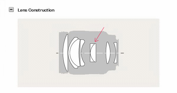
Do you know that the two elements in the center are the apodization filter?
As far as I know these are not working as a lens cause they have the same refractive index, probably even the same glass.
So there are only 6 lenses left. And these lenses have to correct the aberrations created from the thick parallel plate inside the optical system - the apodization filter. |
I suppose you're talking about the doublet with flat or nearly flat faces:
.
I imagine the apodization filter could be just a film applied on one surface of this doublet. The doublet itself has an optical function which has nothing to do with the apodization filter. Generally this kind of doublet is made from glasses with equal or almost equal refractive index, but with different chromatic dispersions. It would make no sense to built a doublet with the same glasses!
If made as described above, the doublet has no or almost no effect on the monochromatic aberrations, but the separation surface can be manipulated to correct residual chromatic aberrations, in particular the spherochromatism.
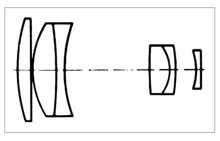
The CZJ 200mm F2.8 and 300mm F4 are some lenses I remember that use that type of optical structure.
CZJ 200mm F2.8 optical diagram:
There is little doubt that a spherical optical surface with greater curvature produces higher aberration. Therefore, one of the most efficient techniques to reduce spherical aberration is to replace a single lens by two thinner ones, as Kingslake says in his book Lens Design Fundamentals:
"A considerable reduction in spherical aberration can be achieved by taking two identical lenses of twice the desired focal length and mounting them close together."
An optical designer uses elements with strong curvature only when they are really needed for some specific reason. The final lens may have little aberration if the designer succeeds in making the aberrations of the multiple optical surfaces cancel each other, even though some strongly curved optical surface has large aberrations itself.
_________________
If raindrops were perfect lenses, the rainbow did not exist. |
|
| Back to top |
|
|
dan_
Joined: 05 Dec 2012
Posts: 1053
Location: Romania
Expire: 2016-12-19
|
| Posted: Wed Jul 23, 2014 6:45 pm Post subject: |
|
|
dan_ wrote:
Of course it was always wide opened.
Just made a quick test right now to show the effect :

What is interesting:
- the position of the center circle in the whole spot of little circle lights is de-centered as the effect appears further of the center of the image
- the effect only affects the out of focus area
- the effect is clear if the glow that creates it is more close to be in-focus
- the effect doesn't appear at all the glows in the image |
|
| Back to top |
|
|
dan_
Joined: 05 Dec 2012
Posts: 1053
Location: Romania
Expire: 2016-12-19
|
| Posted: Wed Jul 23, 2014 7:18 pm Post subject: |
|
|
dan_ wrote:
| Gerald wrote: |
| I imagine the apodization filter could be just a film applied on one surface of this doublet. |
As far as I know the filter is the concave part of the doublet, which is made of grey glass. That is the common way to make quality center variable density filters and the reason they are so expensive. |
|
| Back to top |
|
|
Gerald
Joined: 25 Mar 2014
Posts: 1196
Location: Brazil
|
| Posted: Wed Jul 23, 2014 7:24 pm Post subject: |
|
|
Gerald wrote:
| dan_ wrote: |
| Gerald wrote: |
| Sorry, but I disagree. The very idea behind the apodization filter is to combine the rays that come from the central region of the lens with the attenuated rays that come from the periphery of the lens. Simple as that. |
Have you ever tried it?
I did. I have those masks with very small circles from a Mamiya RB 150mm SF lens and tried them on different lenses. The effect is exactly as ZoneV said : disagreeable small light circles around every light spot. Unless they are microscopical (= impossible do DIY) the wholes will not produce a smooth effect.
Simple as that. |
I did some quick tests and I have to agree with you. Under certain conditions the structure of holes can indeed be visible if the diameter of the holes is not very small. 
However, the idea of using an apodization filter at the front of the lens is still valid, I think.
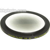
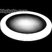
What is needed is a filter with a kind of reverse gradient to that used in Super Angulon lens to correct vignetting:
Linhof filter:

Inverted Linhof filter -a model to a frontal apodization filter:
.
I believe that filter could be home made using a photographic film exposed to an appropriate pattern.
_________________
If raindrops were perfect lenses, the rainbow did not exist. |
|
| Back to top |
|
|
Gerald
Joined: 25 Mar 2014
Posts: 1196
Location: Brazil
|
| Posted: Wed Jul 23, 2014 7:30 pm Post subject: |
|
|
Gerald wrote:
| dan_ wrote: |
| Gerald wrote: |
| I imagine the apodization filter could be just a film applied on one surface of this doublet. |
As far as I know the filter is the concave part of the doublet, which is made of grey glass. That is the common way to make quality center variable density filters and the reason they are so expensive. |
It makes sense and if true it confirms what Markus said before that the two parts of the doublet are made from glasses of same optical properties. 
_________________
If raindrops were perfect lenses, the rainbow did not exist. |
|
| Back to top |
|
|
visualopsins


Joined: 05 Mar 2009
Posts: 10528
Location: California
Expire: 2025-04-11
|
| Posted: Wed Jul 23, 2014 7:35 pm Post subject: |
|
|
visualopsins wrote:
| ZoneV wrote: |
| Probably there is a big sample variation ... |
Could be big variation in focusing technique.  DOF region of wide angle lens is very curved -- of course sharpness depends on edge placement in that region. DOF region of wide angle lens is very curved -- of course sharpness depends on edge placement in that region.
_________________
☮☮☮☮☮☮☮☮☮☮☮☮☮☮☮☮☮☮☮☮☮☮☮☮☮☮☮☮☮☮☮☮ like attracts like! ☮☮☮☮☮☮☮☮☮☮☮☮☮☮☮☮☮☮☮☮☮☮☮☮☮☮☮☮☮☮☮☮
Cameras: Sony ILCE-7RM2, Spotmatics II, F, and ESII, Nikon P4
Lenses:
M42 Asahi Optical Co., Takumar 1:4 f=35mm, 1:2 f=58mm (Sonnar), 1:2.4 f=58mm (Heliar), 1:2.2 f=55mm (Gaussian), 1:2.8 f=105mm (Model I), 1:2.8/105 (Model II), 1:5.6/200, Tele-Takumar 1:5.6/200, 1:6.3/300, Macro-Takumar 1:4/50, Auto-Takumar 1:2.3 f=35, 1:1.8 f=55mm, 1:2.2 f=55mm, Super-TAKUMAR 1:3.5/28 (fat), 1:2/35 (Fat), 1:1.4/50 (8-element), Super-Multi-Coated Fisheye-TAKUMAR 1:4/17, Super-Multi-Coated TAKUMAR 1:4.5/20, 1:3.5/24, 1:3.5/28, 1:2/35, 1:3.5/35, 1:1.8/85, 1:1.9/85 1:2.8/105, 1:3.5/135, 1:2.5/135 (II), 1:4/150, 1:4/200, 1:4/300, 1:4.5/500, Super-Multi-Coated Macro-TAKUMAR 1:4/50, 1:4/100, Super-Multi-Coated Bellows-TAKUMAR 1:4/100, SMC TAKUMAR 1:1.4/50, 1:1.8/55
M42 Carl Zeiss Jena Flektogon 2.4/35
Contax Carl Zeiss Vario-Sonnar T* 28-70mm F3.5-4.5
Pentax K-mount SMC PENTAX ZOOM 1:3.5 35~105mm, SMC PENTAX ZOOM 1:4 45~125mm
Nikon Micro-NIKKOR-P-C Auto 1:3.5 f=55mm, NIKKOR-P Auto 105mm f/2.5 Pre-AI (Sonnar), Micro-NIKKOR 105mm 1:4 AI, NIKKOR AI-S 35-135mm f/3,5-4,5
Tamron SP 17mm f/3.5 (51B), Tamron SP 17mm f/3.5 (51BB), SP 500mm f/8 (55BB), SP 70-210mm f/3.5 (19AH)
Vivitar 100mm 1:2.8 MC 1:1 Macro Telephoto (Kiron)
|
|
| Back to top |
|
|
ZoneV
Joined: 09 Nov 2009
Posts: 1633
Location: Germany
Expire: 2011-12-02
|
| Posted: Wed Jul 23, 2014 8:36 pm Post subject: |
|
|
ZoneV wrote:
| Gerald wrote: |
...
Sorry, but I disagree. The very idea behind the apodization filter is to combine the rays that come from the central region of the lens with the attenuated rays that come from the periphery of the lens. Simple as that.
|
From my point of view the idea is to accentuate the intensity form 100% to 0% as good as possible in a Gaussian curve.
One could do that with holes too, but you need many very small holes - which are not possible to DIY manufacture, and likely result in diffraction as well.
Furthermore it is impossible to make a smoth transition for the transmission 100% to 50% with holes. near the center ther should be 99% holes and 1% structure, ~stepless going to 99% structure to 1% holes - and even less. And this should not be visible in an printet image with bokeh size of 20mm or larger.
| Gerald wrote: |
...
P.S.: Very interesting article, Markus. I like it very much! |
Thank you
| Gerald wrote: |
...
I imagine the apodization filter could be just a film applied on one surface of this doublet. The doublet itself has an optical function which has nothing to do with the apodization filter. Generally this kind of doublet is made from glasses with equal or almost equal refractive index, but with different chromatic dispersions. It would make no sense to built a doublet with the same glasses!... |
I am pretty sure that the two elements are made from same material, one is tinted, the other is grey. So the same optical effect as a plano parallel plate, and this grey filtering. This is what could be found on the internet, I thought I have read this on a Sony page too.
| Gerald wrote: |
...
There is little doubt that a spherical optical surface with greater curvature produces higher aberration. Therefore, one of the most efficient techniques to reduce spherical aberration is to replace a single lens by two thinner ones, as Kingslake says in his book Lens Design Fundamentals:
"A considerable reduction in spherical aberration can be achieved by taking two identical lenses of twice the desired focal length and mounting them close together."
|
Page 184 in the second edition, yes.
This is a reason why lithographic lenses have many lenses with slight curvatures. But still a lot of lenses have strong curvatures - for example to get smaller incidend angles and thus smaller aberrations (not only spherical aberration). The fewer the light rays are bend on a surface, the fewer problems. The strong lens curvatures are no big problem as long as the light rays are still ideal at right angle to the surface. See the Double Gauss design, or a lot of wideangle lenses.
Further sharp Sony STF images:
https://www.flickr.com/photos/hhackbarth/11275961253/sizes/o/
https://www.flickr.com/photos/hhackbarth/13913107390/sizes/o/
_________________
Camera modification, repair and DIY - some links to look through: http://www.4photos.de/camera-diy/index-en.html
I AM A LENS NERD!
Epis, Elmaron, Emerald, Ernostar, Helioplan and Heidosmat.
Epiotar, Kameraobjektiv, Anastigmat, Epis, Meganast, Magnagon, Quinar, Culmigon, Novotrinast, Novflexar, Colorplan, Sekor, Kinon, Talon, Telemegor, Xenon, Xenar, Ultra, Ultra Star. Tessar, Janar, Visionar, Kiptar, Kipronar and Rotelar.
|
|
| Back to top |
|
|
ZoneV
Joined: 09 Nov 2009
Posts: 1633
Location: Germany
Expire: 2011-12-02
|
| Posted: Wed Jul 23, 2014 8:46 pm Post subject: |
|
|
ZoneV wrote:
| visualopsins wrote: |
| ...Could be big variation in focusing technique. DOF region of wide angle lens is very curved -- of course sharpness depends on edge placement in that region. |
135mm for 24x36mm sensor is not a very wide wideangle lens
But after reviewing the bad images it could be that at the very high megapixel number the "infinity" is farther away than I would have thought. Need to calculate this with pixel size.
_________________
Camera modification, repair and DIY - some links to look through: http://www.4photos.de/camera-diy/index-en.html
I AM A LENS NERD!
Epis, Elmaron, Emerald, Ernostar, Helioplan and Heidosmat.
Epiotar, Kameraobjektiv, Anastigmat, Epis, Meganast, Magnagon, Quinar, Culmigon, Novotrinast, Novflexar, Colorplan, Sekor, Kinon, Talon, Telemegor, Xenon, Xenar, Ultra, Ultra Star. Tessar, Janar, Visionar, Kiptar, Kipronar and Rotelar.
|
|
| Back to top |
|
|
Gerald
Joined: 25 Mar 2014
Posts: 1196
Location: Brazil
|
| Posted: Thu Jul 24, 2014 12:58 am Post subject: |
|
|
Gerald wrote:
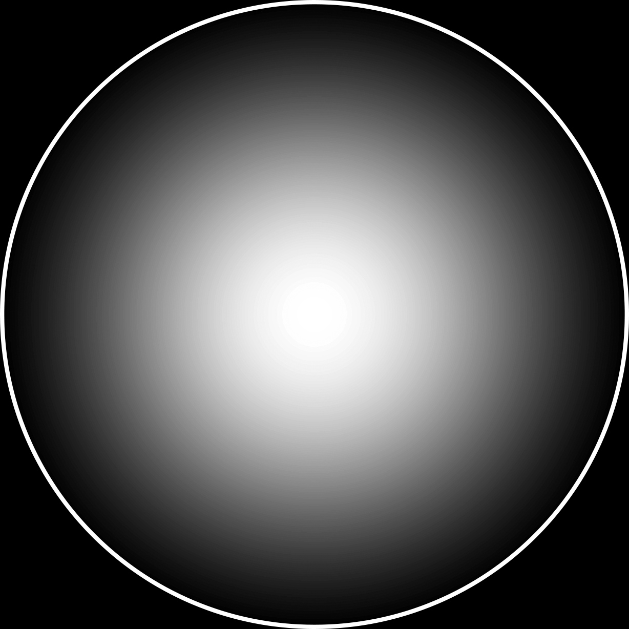
Out of curiosity, I did a quick-and-dirty quick experiments with a homemade apodization filter. First I drew a pattern with Photoshop and print it with a LaserJet printer on a transparency. Then I cut out the filter from the transparency sheet, mounted on a UV 55mm filter and put the "filter" on a 135mm lens.
The result? Terrible!
The problem was not the filter itself but the transparency that diffuse light too much. I think that a B&W negative film negatives, photolithographic film, or a slide could be a little better, but not much. The biggest problem to improvise an apodization filter seems to find a proper substrate to print it.
Below the pattern I used. If printed with a 600 dpi printer it should generate a circle with diameter of 52mm.
_________________
If raindrops were perfect lenses, the rainbow did not exist. |
|
| Back to top |
|
|
ZoneV
Joined: 09 Nov 2009
Posts: 1633
Location: Germany
Expire: 2011-12-02
|
| Posted: Thu Jul 24, 2014 6:50 am Post subject: |
|
|
ZoneV wrote:
| Gerald wrote: |
| ...The problem was not the filter itself but the transparency that diffuse light too much. I think that a B&W negative film negatives, photolithographic film, or a slide could be a little better, but not much. The biggest problem to improvise an apodization filter seems to find a proper substrate to print it... |
Yes, the material is a nain factor. Wron material gives a lot of stray light.
Some stray light is acceptable for me, but I made several tests with wrong material.
_________________
Camera modification, repair and DIY - some links to look through: http://www.4photos.de/camera-diy/index-en.html
I AM A LENS NERD!
Epis, Elmaron, Emerald, Ernostar, Helioplan and Heidosmat.
Epiotar, Kameraobjektiv, Anastigmat, Epis, Meganast, Magnagon, Quinar, Culmigon, Novotrinast, Novflexar, Colorplan, Sekor, Kinon, Talon, Telemegor, Xenon, Xenar, Ultra, Ultra Star. Tessar, Janar, Visionar, Kiptar, Kipronar and Rotelar.
|
|
| Back to top |
|
|
dan_
Joined: 05 Dec 2012
Posts: 1053
Location: Romania
Expire: 2016-12-19
|
| Posted: Thu Jul 24, 2014 8:36 am Post subject: |
|
|
dan_ wrote:
| Gerald wrote: |
Out of curiosity, I did a quick-and-dirty quick experiments with a homemade apodization filter. First I drew a pattern with Photoshop and print it with a LaserJet printer on a transparency. Then I cut out the filter from the transparency sheet, mounted on a UV 55mm filter and put the "filter" on a 135mm lens.
The result? Terrible! |
I did this experiment too, some time ago, with the same results as yours.
Then I've searched for a method to transfer the laser print on the glass of an UV filter.
There is a thermal method, I tried it and it broke the glass of the UV filter
There are some chemical methods too, but I've never tried them.
This kind of transfer from a laser print is used for etching the glass and for electrical circuits (DIY).
Maybe someone knows a better method of transfer. |
|
| Back to top |
|
|
ZoneV
Joined: 09 Nov 2009
Posts: 1633
Location: Germany
Expire: 2011-12-02
|
| Posted: Thu Jul 24, 2014 9:28 am Post subject: |
|
|
ZoneV wrote:
Additional glass inside the lens is a problem. This is a reason why I used film which is thin relative to most glass.
_________________
Camera modification, repair and DIY - some links to look through: http://www.4photos.de/camera-diy/index-en.html
I AM A LENS NERD!
Epis, Elmaron, Emerald, Ernostar, Helioplan and Heidosmat.
Epiotar, Kameraobjektiv, Anastigmat, Epis, Meganast, Magnagon, Quinar, Culmigon, Novotrinast, Novflexar, Colorplan, Sekor, Kinon, Talon, Telemegor, Xenon, Xenar, Ultra, Ultra Star. Tessar, Janar, Visionar, Kiptar, Kipronar and Rotelar.
|
|
| Back to top |
|
|
Gerald
Joined: 25 Mar 2014
Posts: 1196
Location: Brazil
|
| Posted: Thu Jul 24, 2014 2:35 pm Post subject: |
|
|
Gerald wrote:
| dan_ wrote: |
[I did this experiment too, some time ago, with the same results as yours.
Then I've searched for a method to transfer the laser print on the glass of an UV filter.
There is a thermal method, I tried it and it broke the glass of the UV filter
There are some chemical methods too, but I've never tried them.
This kind of transfer from a laser print is used for etching the glass and for electrical circuits (DIY).
Maybe someone knows a better method of transfer. |
I have built several PC boards using the tone transfer method. There are many improvised techniques described on the web but in general they are unreliable (and frustrating...). I have used a transfer paper from Pulsar Pro FX that works like a charm. It seems that the paper is coated with a kind of gelatin which dissolves in water, eliminating the major problem of tone transfer method that is detaching the toner from the transfer sheet.
An envelope with 10 sheets of Tone Transfer Paper costs $15. The transfer can be made with a common domestic iron (the method I have used).
Links to the product:
http://www.pcbfx.com/main_site/pages/products/transfer_paper.html
http://www.pcbfx.com/main_site/pages/tech_support/instructions/3_iron_calibration.html
http://www.pcbfx.com/main_site/store/index.html
I never did toner transfer to an UV filter, but I think it is perfectly possible as long as certain precautions are taken, such as taking out previously the filter glass from the metal ring.
I believe that an UV filter can resist the thermal shock from the heat of an iron, but never did that experience to know for sure.
I don't know if the tone transfer method has the precision needed to make a good gradient filter. What I know is that it is perfectly possible to make PCB tracks with some tenths of a millimeter.
Finally, if something goes wrong with the tone transfer, simply wipe with thinner and do it again.
_________________
If raindrops were perfect lenses, the rainbow did not exist. |
|
| Back to top |
|
|
dan_
Joined: 05 Dec 2012
Posts: 1053
Location: Romania
Expire: 2016-12-19
|
| Posted: Thu Jul 24, 2014 3:47 pm Post subject: |
|
|
dan_ wrote:
Thanks for the info, Gerald.
I think a front-mounted apodisation filter is feasible this way.
Probably the Photoshop image should be transformed in duo-tones and printed in B&W for the best results and the glass of the filter should be pre heated in order to resist. |
|
| Back to top |
|
|
Gerald
Joined: 25 Mar 2014
Posts: 1196
Location: Brazil
|
| Posted: Sun Jul 27, 2014 8:40 pm Post subject: |
|
|
Gerald wrote:
Sony 135mm T4.5 STF mistery solved!
What I mean by "mystery" is: Why does such an expensive lens like the Sony 135mm T4.5 STF have a performance below average in the corners?
When Kurt Munger reviewed the Sony STF, he made the following remark: "The soft corners wide open with a full frame camera are a little surprising, but look fine at F/8."
My analysis of photos taken with that lens wide open confirmed Munger's observation. If you disagree with Munger, and are really convinced that the Sony STF is a super sharp lens, you do not need to keep reading. In any case, please make sure that I do not want to belittle the Sony 135mm T4.5 lens, which I think is an interesting lens. However, it is clear to me that its design implied a trade-off between sharpness in the corners and pleasing bokeh.
The key to understand the "mystery" of the Sony STF is the following statement from the Sony Alpha lens book:
"The 135mm F2.8 [T4.5] STF has an exceptionally large diameter (72mm filter size) for a fixed focal length lens, ensuring high aperture efficiency with virtually no vignetting. Even with the aperture fully opened, defocusing is superb right up to the periphery of the image."
Excerpt from: http://www.dyxum.com/columns/articles/lenses/sal-135f28/sony-af-135-stf-sal-135f28_review.asp
Consider that a 135mm F2.8 lens requires an aperture of only 135 / 2.8 = 48.2mm, so 72mm appears to be overkill. So why does the Sony 135 STF use a 72mm filter, which is much larger than the typical 52-55mm filter used in most 135mm F2.8 lens?
The reason for Sony STF uses oversized front optical elements is to minimize vignetting.
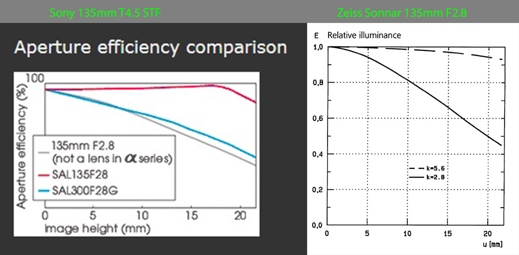
If you take a look at the graph below you will notice that the illuminance on the Sony STF (red curve) is nearly constant across the field. In comparison, the Zeiss Sonnar 135mm F2.8 for Contax/Yashica suffers from strong light fall-off more wide open. For the Sonnar, the illuminance in the corners drops to almost 40% compared with the center.

Why uniform illuminance (no fall-off) is so important in a STF lens
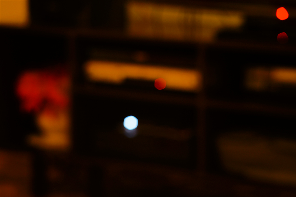
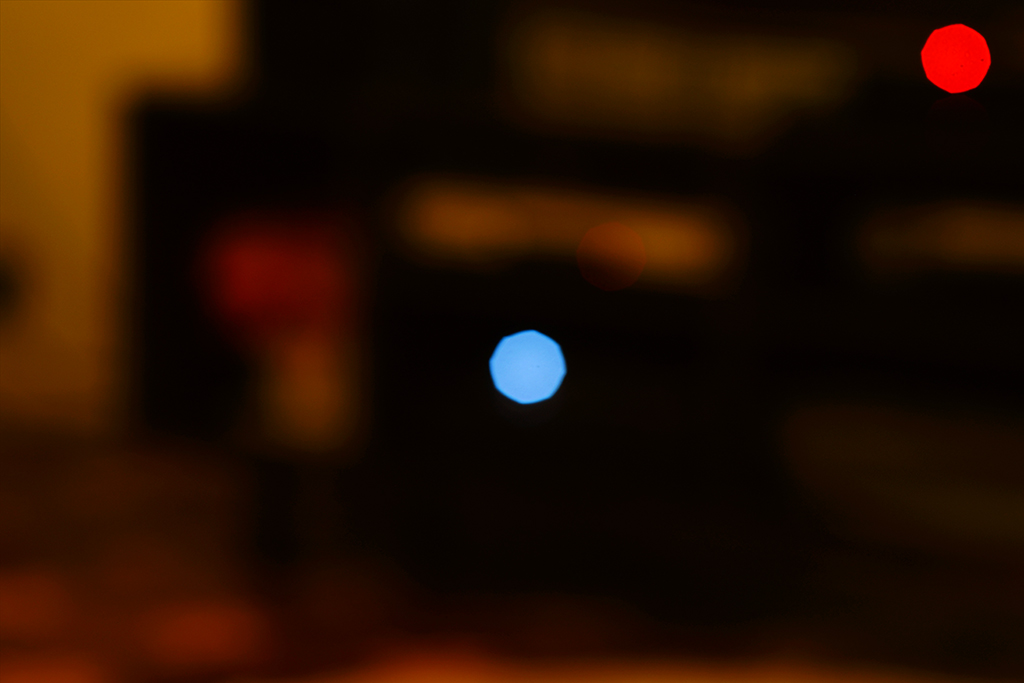
The best way to understand why uniform illuminance is important to a STF lens is observing how a non-STF 135mm lens renders the image of an defocused point source. Take, for example, a Pentacon 135mm F2.8 lens when wide open. The photograph below shows that the light blue point source in the center is rendered as a uniform circle, while the red point source in the corner as an oval shape due to vignetting by the front and rear lenses of moderate diameter (incidentally, the ratio between the areas of the two circles gives the relative illuminance, which is around 50% for the Pentacon lens).
Pentacon 135mm F2.8 at F2.8 (wide open):
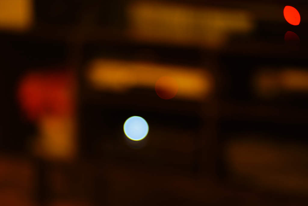
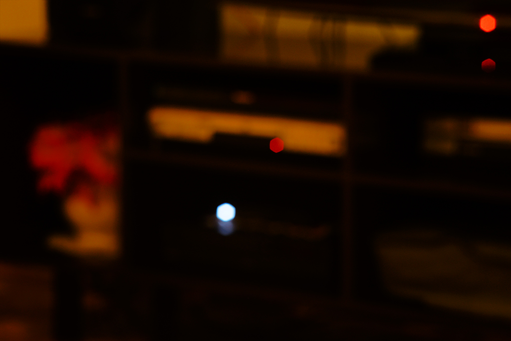
The pictures below show the blurs when the lens diaphragm is closed to F4, F5.6 and F8. The out-of-focus images acquire a hexagonal shape as the Pentacon has a 6-blade diaphragm. The vignetting disappears completely by F8 or smaller apertures.
Pentacon 135mm F2.8 at F4:

Pentacon 135mm F2.8 at F5.6:

Pentacon 135mm F2.8 at F8:

A key point is to understand what happens when if STF suffers from vignetting
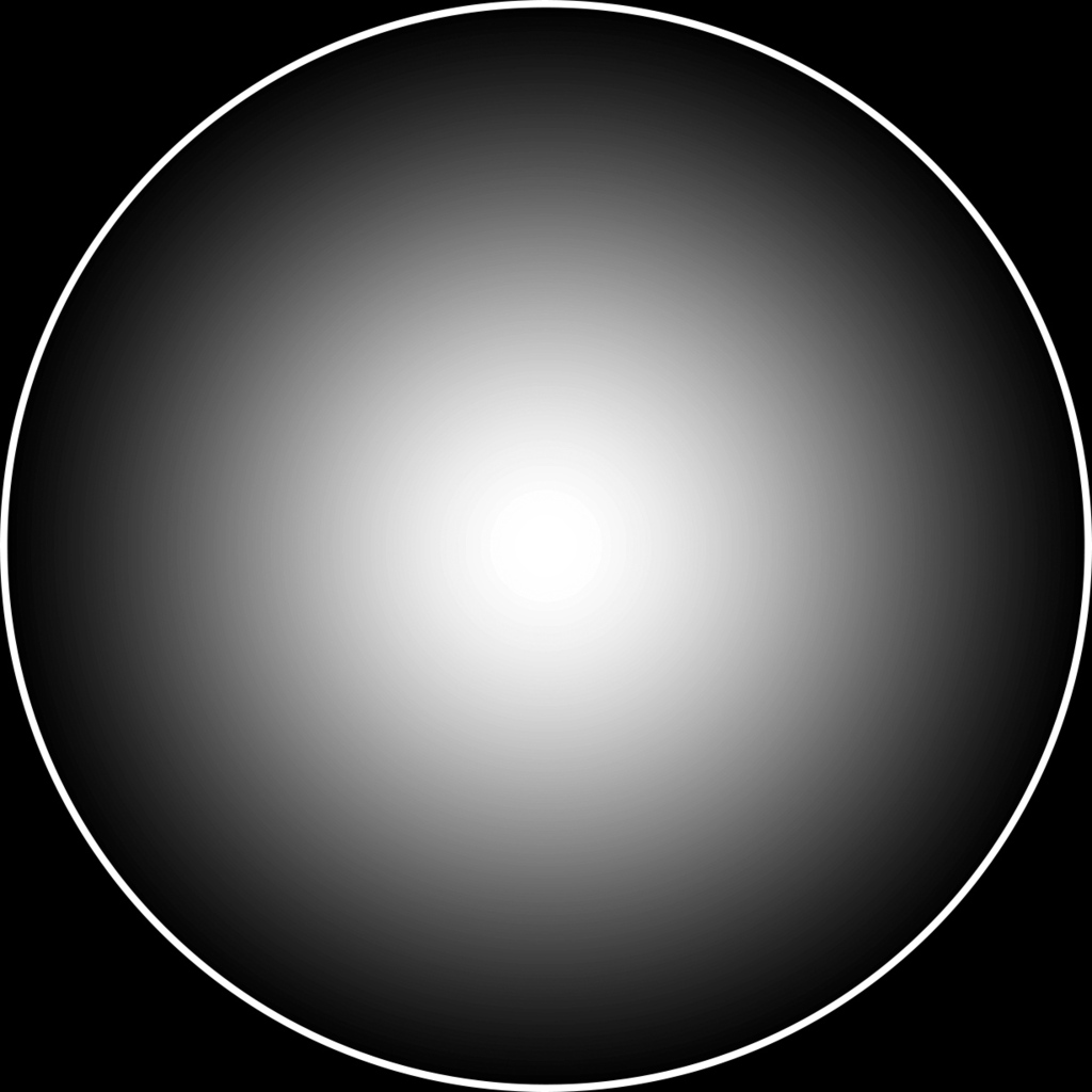
The figure below shows a simulation of the image of a defocused point source, as produced by a STF lens with a gradient filter. The blur at the left is for the case where no vignetting occurs (center of the frame always, or corner when there is not light fall-off). Note that the blur shape is circular and edges are fuzzy, what should produce excellent bokeh.
The blur at the right represents the defocused image of a point source in the corner for a lens that suffers from significant vignetting. Note that vignetting causes the blur to gain a well-defined boundary, which will certainly have a negative effect on the quality of the bokeh.
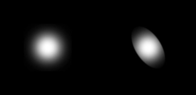
A conclusion we can draw is that an STF lens should not suffer from any significant vignetting; otherwise, the quality of the bokeh at edges and corners will be greatly impaired.
At this point, I believe it is quite clear why the designers of the Sony 135mm STF lens had to use front and rear optical elements with much larger than usual diameters. If they had not done so, vignetting would occur and the bokeh at the corners would be nothing better than an average135mm lens.
Unfortunately, the increase in the diameter of the optical elements has a price to be paied, which is the increase in the aberration at the edges and corners. Indeed, the lens designers often introduce vignetting to reduce, among other reasons, the off-axis aberrations. The vignetting is beneficial because it cuts the most oblique rays that produce the most horrible aberrations. By allowing the passage of these rays to reduce vignetting, the designer necessarily increases the level of aberrations at the edges and corners.
The Sony STF lens could produce a high-quality image at the edges and corners if the designers had used a larger number of optical elements to better correct off-axis aberrations. Unfortunately, the Sony STF lens already has 8 optical elements (two elements are to implement of gradient filter, so 6 elements are left to correction of aberrations), so adding additional optical elements would greatly increase the weight, size and cost of the lens. The designers of the Sony STF probably thought that the sacrifice of quality was acceptable for most users that think that resolution in the edges and corners is less important than a pleasing bokeh.
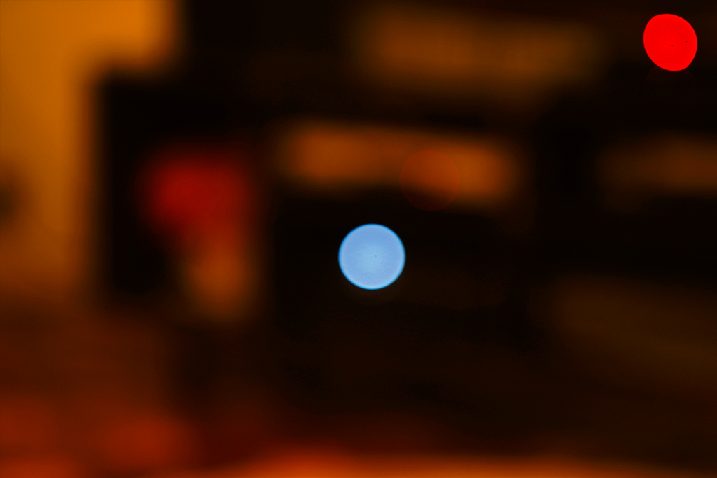
Just out of curiosity, I show below the pictures produced by a CZJ Biometar 120mm F2.8, whose focal length is only a little smaller than the Sony STF. Note that the shape of the blur at the corner is almost circular at F2.8, showing that the vignetting is small even for the lens wide open. For F4 on, vignetting is simply nonexistent. Hence, the Biometar 120mm would be a good candidate for implementing an STF lens.
CZJ Biometar 120mm F2.8 at F2.8 (wide open):

CZJ Biometar 120mm F2.8 at F4:

_________________
If raindrops were perfect lenses, the rainbow did not exist. |
|
| Back to top |
|
|
calvin83

Joined: 12 Apr 2009
Posts: 7553
Location: Hong Kong
|
| Posted: Mon Jul 28, 2014 4:47 am Post subject: |
|
|
calvin83 wrote:
It is a well known fact here Minolta use oversize lens elements to reduce optical vignetting on the STF.
The Biometar is a medium format lens. The vignetting will be much less visible when it is used on 35mm camera.
_________________
https://lensfever.com/
https://www.instagram.com/_lens_fever/
The best lens is the one you have with you. |
|
| Back to top |
|
|
dan_
Joined: 05 Dec 2012
Posts: 1053
Location: Romania
Expire: 2016-12-19
|
| Posted: Mon Jul 28, 2014 10:17 am Post subject: |
|
|
dan_ wrote:
| Gerald wrote: |
| Sony 135mm T4.5 STF mistery solved! |

Kalvin83 is right, the fact that Minolta used oversize lens elements to reduce optical vignetting on the STF is well known.
The reason why the "cat eyes" effect appears is very well (and in a simple way) explained here:
http://rafimoor.com/english/bokehe.htm (see drawing 3 and its explanation)
IMO your explanation, Gerald, seams correct with two little amendments:
- "a 135mm F2.8 lens requires an aperture of only 135 / 2.8 = 48.2mm" is not correct. The f-number N is given by N=f/D where f is the focal length, and D is the diameter of the entrance pupil; 48.2mm is not the required aperture of the a 135 / 2.8 lens but the required diameter of its entrance pupil and the entrance pupil is an image, not the diameter of the front lens.
- The image :
is not correct because the well defined boundary should only be seen on the outer side of the peripheral light spot. Its inner side, the one bounded by the aperture, will remain a smooth transition, as it is on the other light spot. |
|
| Back to top |
|
|
Gerald
Joined: 25 Mar 2014
Posts: 1196
Location: Brazil
|
| Posted: Mon Jul 28, 2014 2:22 pm Post subject: |
|
|
Gerald wrote:
| calvin83 wrote: |
| It is a well known fact here Minolta use oversize lens elements to reduce optical vignetting on the STF. |
If you read my post carefully you will see that I did not say I "discovered" that Sony STF lens uses oversized optical elements. Of course that was already known. Sony even bragged about it!
My point was that the use of oversized optical elements is the underlying cause of the poor resolution at edges and corners. I believe that the relation between poor performance in the edges and corners and oversized optical elements has never been discussed before, at least for the Sony STF lens.
_________________
If raindrops were perfect lenses, the rainbow did not exist. |
|
| Back to top |
|
|
|
|